
Photodiode current-to-voltage converter
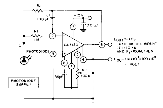
The photodiode current-to-voltage converter is an essential component in optical detection systems, where precise measurement of light intensity is required. The CA3130 BiMOS op-amps are chosen for their low input bias current and high input impedance, making them ideal for detecting very low currents generated by photodiodes in response to light.
In this configuration, the photodiode is connected in reverse bias mode, which enhances its response speed and linearity. The output voltage from the op-amps is determined by the relationship between the photodiode current and the feedback resistor connected to the output. The gain of the circuit can be adjusted by changing the value of the feedback resistor, allowing for flexibility in the sensitivity of the system.
The circuit design incorporates additional features to minimize noise and improve stability. For example, bypass capacitors may be employed at the power supply pins of the op-amps to filter out high-frequency noise. Additionally, careful layout considerations are necessary to reduce parasitic capacitance and inductance that could affect the performance of the circuit.
Overall, this photodiode current-to-voltage converter circuit is vital for applications such as optical communication, spectroscopy, and light measurement in various scientific and industrial fields, where accurate and reliable detection of low light levels is crucial.The Photodiode current-to-voltage converter circuit uses three CA3130 BiMOS op amps in an application sensitive to sub-picoampere input currents. The circuit provides a ground-referenced output voltage proportional to input current flowing through the photo-diode.
🔗 External reference
Related Circuits

In some cases, it is necessary to power a circuit from a battery, where the required supply voltage falls within the battery's discharge curve. A new battery provides a higher voltage than needed, while a battery nearing the end...
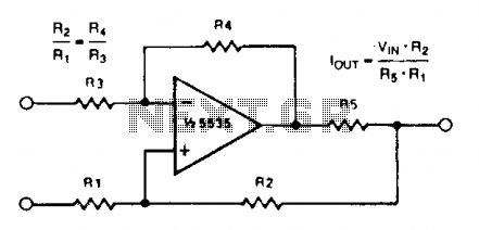
A simple voltage-to-current converter is illustrated. The output current is given by 0t or Vjn/R. For negative currents, a PNP transistor can be employed, and for improved accuracy, a Darlington pair can replace the transistor. With meticulous design, this...
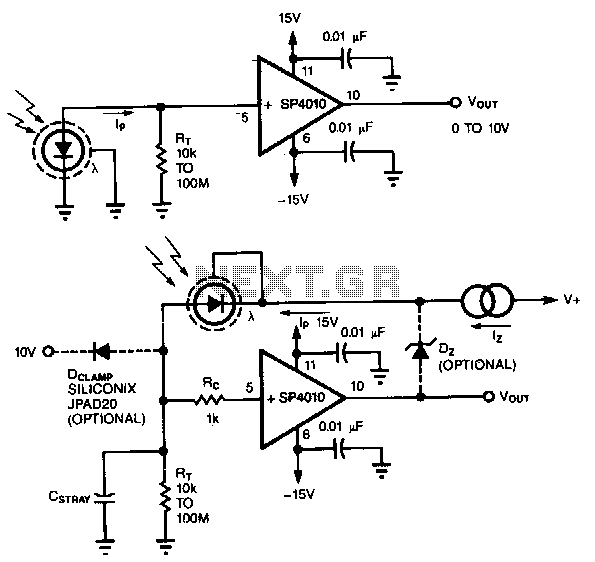
A common method of transforming the output current of a photodiode into a voltage signal involves paralleling the photodiode with a high-value load resistor, which results in a nonlinear response. Additionally, the combination of the load's transresistance, Rr, and...
A voltage-to-frequency converter (VFC) circuit is illustrated in the schematic diagram below. The circuit utilizes a 555 integrated circuit (IC) as the central component of its operation. The voltage-to-frequency converter (VFC) is a crucial electronic circuit that converts an input...
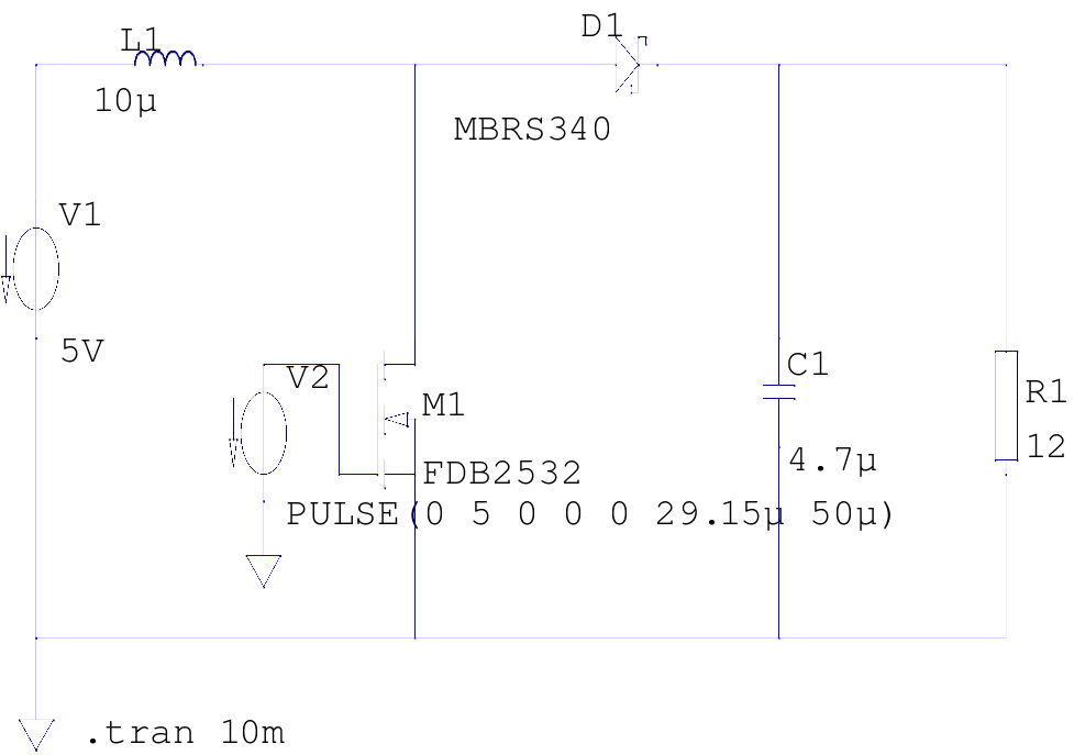
The supply voltage is 5V, and the goal is to increase it to 12V with a load current of 1A, resulting in an output power of 12W. A switching frequency of 20kHz has been selected, requiring a duty cycle...
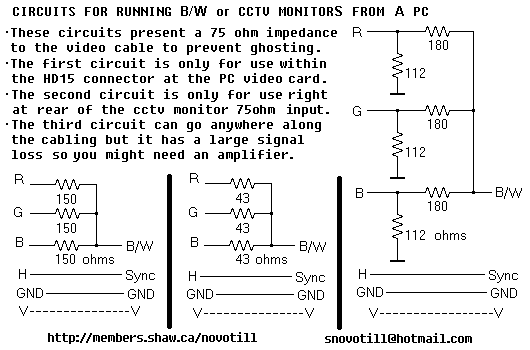
Often you can get away with running a monochrome monitor on GREEN, but this looks real crappy when viewing color images. These simple resistor networks allow you to display R+G+B on a B/W or CCTV monitor without ghosting. Be...
Warning: include(partials/cookie-banner.php): Failed to open stream: Permission denied in /var/www/html/nextgr/view-circuit.php on line 713
Warning: include(): Failed opening 'partials/cookie-banner.php' for inclusion (include_path='.:/usr/share/php') in /var/www/html/nextgr/view-circuit.php on line 713