
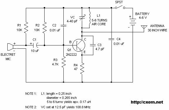
FM Wireless Microphone

The circuit utilizes a straightforward design that integrates both amplification and frequency modulation to facilitate wireless audio transmission. The MAX4467 serves as the primary audio amplifier, ensuring that the microphone's output is sufficiently boosted for effective modulation by the VCO. The choice of a high-Q inductor for L1 is critical, as it directly influences the stability and performance of the oscillator. This inductor, along with the varactor diode, forms a resonant circuit that is finely tuned to achieve the desired frequency range.
The use of a potentiometer for channel selection enhances user control, allowing the experimenter to navigate the FM band easily. The incorporation of a low-noise VCO like the MAX2606 ensures that the transmitted signal remains clear and free from unwanted noise, which is essential for maintaining audio quality in wireless applications.
In terms of construction, attention to detail is paramount. Short traces and careful placement of components are necessary to mitigate the effects of stray capacitance, which could otherwise degrade the performance of the circuit. The design's ability to operate on a low voltage makes it particularly suitable for battery-powered applications, extending its usability for portable projects.
Overall, this project exemplifies an effective approach to creating a basic wireless audio transmission system, combining essential components to achieve a functional and reliable cordless microphone solution.Here is a very simple, inexpensive and interesting project which provides lot of fun to a home experimenter or hobbyist. This simple transmitter can transmit speech over a short range. It can be used as a simple cordless microphone. The circuit uses two integrated circuits from Maxim. IC1 a MAX4467, is an amplifier raising the microphone signal to a level suitable for frequency modulation (FM). IC2 is a voltage-controlled oscillator (VCO) with integrated varactor (a. k. a. varicap diode). Its nominal frequency of oscillation is set by inductor L1. The inductor value 390 nH provides an oscillation frequency of about 100 MHz. For best performance, L1 should be a high-Q component. L1 may consist of 4 turns of silver-plated wire wound around a 10-mm drill bit, and stretched to a length of about 1. 5 cm. The wire diameter can be anything between 26 SWG (0. 5 mm) and 20 SWG (1 mm). No core is used. The MAX4467 is a micro-power opamp for low voltage operation and providing 200-kHz gain bandwidth at a supply current of just 24 µA.
When used with an electret microphone, some form of DC bias for the microphone capsule is necessary. The MAX4467 has the ability to turn off the bias to the microphone when the device is in shutdown mode. This can save several hundred micro-amps of supply current, which can be significant in low power applications particularly for battery powered applications like cordless microphones.
The MIC-Bias pin provides a switched version of Vcc to the bias components. Resistor R1 resistor limits the current to the microphone element. The output impedance of the MAX4467 is low and well suited to driving cables over distances up to 50 m. The MAX2606 intermediate-frequency (IF) voltage-controlled oscillators (VCO) has been designed specifically for portable wireless communication systems.
The IC comes in a tiny 6-pin SOT23 package. The low-noise VCO features an on-chip varactor and feedback capacitors that eliminate the need for external tuning elements. Only an external inductor (here, L1) is required to set the oscillation frequency and produce a properly operating VCO.
To minimize the effects of parasitic elements, which degrade circuit performance, place L1 and C5 close to their respective pins. Specifically, place C5 directly across pins 2 (GND) and 3 (TUNE). Potentiometer P2 then lets you select a free channel by tuning over the FM band of 88 MHz to 108 MHz.
Output power is about 21dBm (approx. 10 µW) into 50 . P1 serves as a volume control by modulating the RF frequency. Signals above 60mV introduce distortion, so the pot attenuates from that level. To decrease stray capacitance, minimize trace lengths by placing external components close to IC1`s pins. Using a wire antenna of about 75 cm the transmitter should have a range of about 35 m. Try to keep all leads as short as possible to prevent stray capacitance. The transmitter operates on a single supply voltage in the range 4. 5 V to 5. 5 V from any standard battery source. The transmitter must be housed in a metal case, with shielding installed between the two stages (AF and RF).
Try to keep all leads as short as possible to prevent stray capacitance. 🔗 External reference
Related Circuits
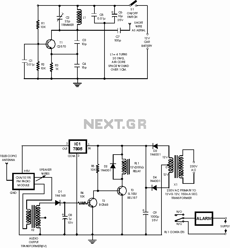
This circuit is a wireless car alarm system that consists of two modules: a transmitter and a receiver. It operates on FM radio waves and is suitable for vehicles with a 6-12V DC power supply. A voltage stabilizer can...
Wireless FM Transmitter. The image displays a wireless FM transmitter alongside a pocket radio and a yellow disk for size comparison. When the user speaks into the transmitter, others can hear the transmission on any FM radio. The wireless FM...
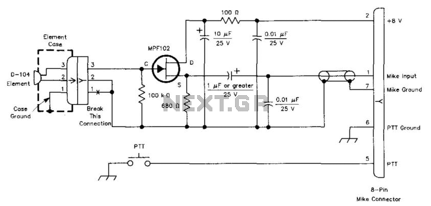
This circuit is designed to interface a high-impedance microphone with a radio transceiver that requires a low-impedance microphone. The power supply can be provided either by a battery or sourced from the transceiver itself. This circuit typically employs a preamplifier...
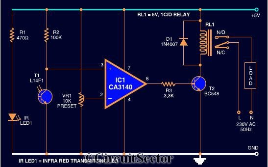
The circuit diagram presented is a highly sensitive wireless relay switch designed to control home appliances such as flush systems and hand dryers. This wireless switch operates without the need for a remote control. It functions by simply moving...
This wireless infrared (IR) headphones circuit project enables the transmission of audio signals through an infrared connection. The circuit consists of two main components: a transmitter and a receiver. Unlike radio frequency (RF) transmitters, both parts of this application...

This is an FM wireless transmitter circuit designed to operate a microphone without the need for a cable connecting the microphone to the amplifier. The FM wireless transmitter circuit typically consists of several key components: a microphone, an oscillator, a...