
MicroPower Solar Engine

The circuit operates on a simple principle of controlling a pager motor using a low-voltage DC source. The design relies on bipolar junction transistors (BJTs) to manage the activation and deactivation of the motor based on the voltage levels. The transistors Q1, Q2, and Q3 form a basic amplification stage that responds to the input voltage, while Q4 serves as the main switching transistor that drives the motor.
When the circuit is powered, the initial voltage rise activates the motor momentarily. This is crucial for ensuring that the motor receives sufficient current to start without drawing excessive power, which could exceed the power source's capabilities. The capacitor discharges quickly, allowing for a brief motor operation while maintaining the transistors Q1 and Q2 in a conductive state. This configuration helps to stabilize the operation and prevent the motor from drawing too much current continuously.
The selection of resistor values, particularly R1 and R6, plays a significant role in the circuit's performance. R1's value influences the base current flowing into Q1 and Q2, while R6 limits the base current for Q4, thus impacting the overall current available to the motor. The recommendation to use a 680K resistor instead of a potentiometer simplifies the design and enhances reliability by reducing potential points of failure.
The suggestion to replace Q4 with a ZTX618 transistor is noteworthy, as this component is designed for higher efficiency and could lead to better performance in terms of voltage across the motor. However, the cost-benefit analysis of this change should be considered, especially in low-budget or prototype applications.
In summary, the circuit design effectively utilizes low-voltage components to drive a pager motor, with careful consideration given to resistor values and transistor selection to optimize performance while maintaining simplicity and reliability.If you have a power source which will provide 2. 5Vdc at 10uA this circuit should drive a pager motor. It turns on the motor at 2. 3 to 2. 5Vdc and switches off at 1. 2 to 1. 5Vdc. Both Steve and I have built ( bread boarded or haywired) the business end of the design and achieved similar results. This does not mean that it will work for everyone but it should. [I used a BC559C (Q1), a BC549C (Q2) a BC559B (Q3) and a BC337-25 (Q4), which happened to be in the bitbox. SB] Enable power to the circuit. If the circuit works properly, the voltage will rise to a firing point, turn on the motor momentarily which discharges the capacitor to level where motor has little current passing through it but Q1 and Q2 are still conducting. At this point, . In practice, I removed R1, measured its value and replaced it with a standard resistor value 5 to 10% less.
560K was the value that both Steve and I used which shows just how repeatable this design is or how lucky we were. Note: It is realized that this presentation is very cryptic. If it were delayed until a complete circuit description and circuit layout were complete, it may not have been presented at all.
It is hard for many to realize the time and effort it takes to create the circuit cards, obtain the correct parts, make up the kits and write assembly / debug instructions. The dollar cost and other risks are not minimal. The first results from building a number of units. It was found that R1 could be replaced with a 680K resistor rather than using a pot. R6 was added to limit the current used to drive the base of Q4 which meant that more current became available for the motor.
390 Ohms is the smallest value that should be used for R6, it can be larger depending upon the motor and drive transistor (Q4) combination. There is one further proposed change that could improve the overall efficiency but it has not been tried, as far as I know.
Changing Q4 to a ZTX618 improves the voltage across the motor. It is manufactured by Zetex and available from Digi-Key, but the trouble and the price ($1. 08 US) may just not be worth it. 🔗 External reference
Related Circuits
Make your own solar powered robot at home using things you probably already have. Transistors, resistor, capacitor, solar battery and flashing LED are available at any electronic store, if you don't already have them. Solar cells out of calculators...
The 1381 solar engine uses a 1381 voltage detector (a.k.a., a voltage supervisor) IC to drive a voltage-based (type 1) solar engine. The 1381 is normally used to reset CPUs and micros when the power supply drops too low...
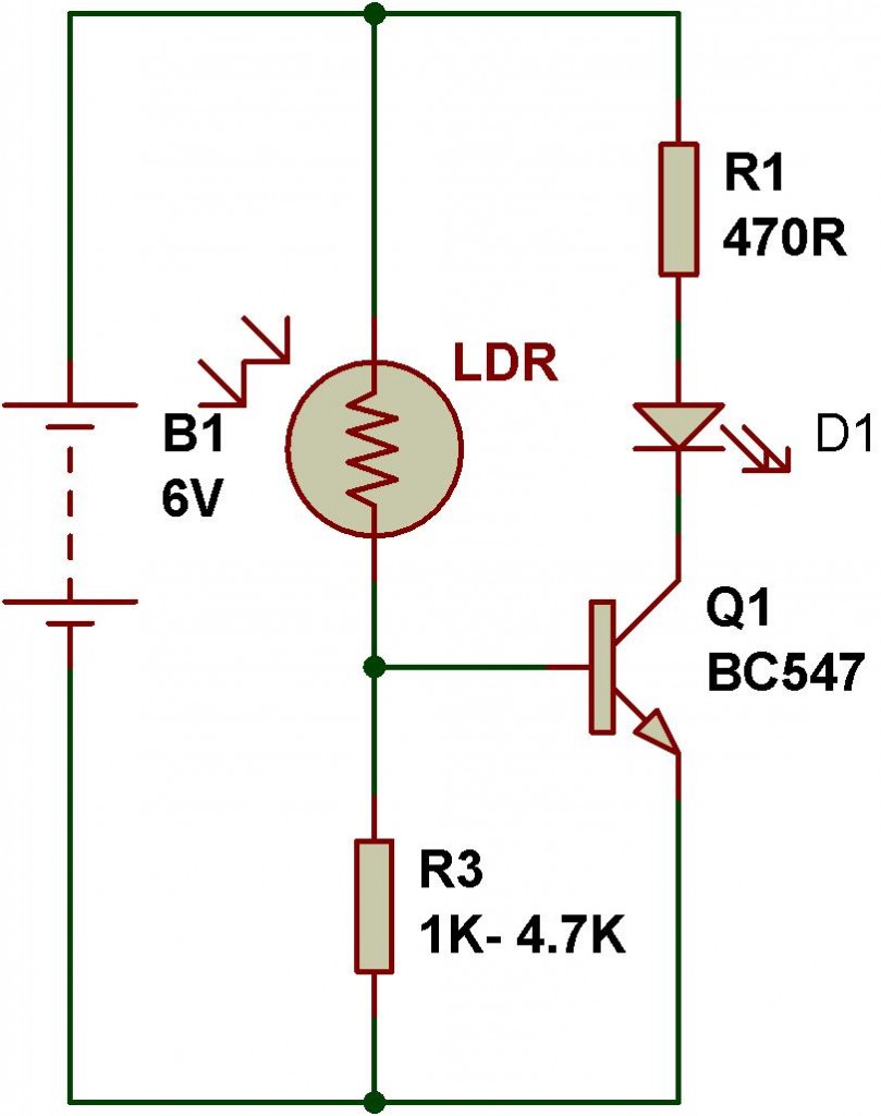
LDR (Light Dependent Resistor) engineering involves creating various electronic circuits based on the principles of a simple light and dark sensor using transistors, the 555 timer IC, and the 741 operational amplifier IC. Among the various optical sensors, the...
The 5W/6V solar panel can achieve a maximum current of approximately 500 to 800mA, peaking at 800mA during noon. Limiting the current to 150mA appears inefficient. A 1W panel can supply around 160mA during peak performance for up to...
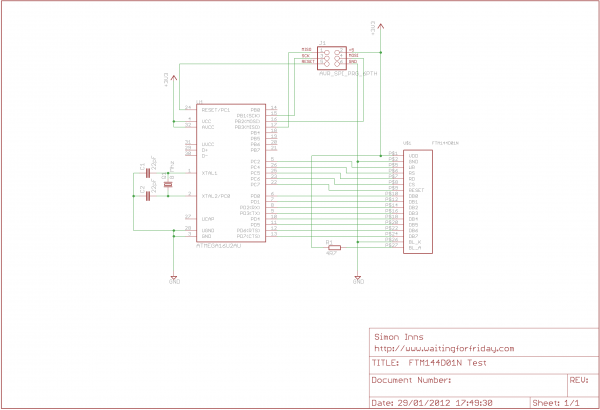
These small devices featured a 1.5-inch 128x128 color TFT display, USB connectivity, batteries, and 16 Mbytes of storage capable of holding approximately 140 pictures. They were inexpensive, prompting the purchase of several units for potential repurposing. An examination of...
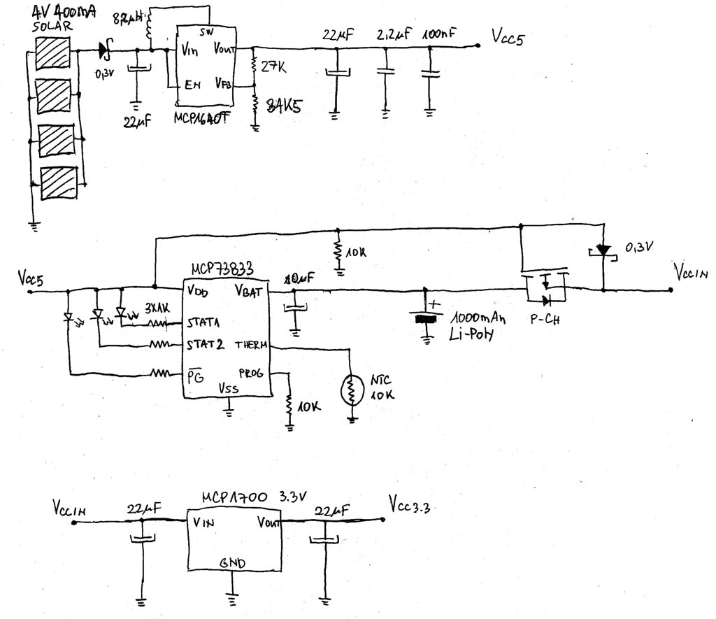
A solar and battery-powered FSK transmitter is designed with a focus on the power supply section, including battery management. The primary objective is to charge the battery and supply power to the transmitter during the day using solar cells,...