
Portable Solar Powered Lantern Circuit
The circuit design utilizes a 5W/6V solar panel as the primary energy source, capable of providing a peak current of 800mA under optimal sunlight conditions. To maximize efficiency, the system can be designed to operate at a lower current draw, ideally around 150mA, although this may not fully utilize the panel's capacity. A more practical approach would involve integrating a 1W solar panel, which can deliver approximately 160mA during peak sunlight hours for a duration of 6 hours. This allows for flexibility in design, particularly in applications where energy consumption needs to be minimized.
For the lighting component, a series configuration of two LEDs per string can be employed, with ten strings connected in parallel. Each string operates at 8mA, resulting in a total current draw of 80mA. This configuration not only enhances brightness but also ensures that the system remains within the operational limits of the solar panel and battery. The total light output from this arrangement can reach approximately 100 lumens, with each LED contributing between 4 to 5 lumens. To optimize performance, a current-limiting resistor can be added in series with each string to fine-tune the brightness, potentially increasing the output to 6 lumens per LED.
The incorporation of an SPST switch allows for manual control of the circuit, enabling the user to turn the system on or off as needed. However, care should be taken to minimize the number of components in the circuit to avoid excessive voltage drops and power loss, particularly through resistors. A well-designed circuit should balance the number of components with the desired performance, ensuring that the overall system remains efficient and cost-effective while providing reliable illumination.The panel 5W/6v Wp will have a max current of approx 500 to 800mA peaking at 800mA at noon. by restricting it to 150mA seems sheer waste. you can use a 1W panel to provide you 160mA at peak performance of 6 hours, to cover for the worst case scenario maybe 2W would be fine. thus reducing the cost of the panel. The 1W LED will give approx 80 to 1 00 Lumens this can be provided by use of a series of 2 LED`s in a strings and have 10 strings each string @8mA for Ultra brightness so the consumption is reduced to 80mA. the battery would last for 6 hours providing illumination of approx 100 Lumens (each LED @4/5 Lumens and you can get 6 Lumens by adding a current limiting resistor in series with each string Too many components after the SPST warming the circuit wasting it in the 5W resistors
🔗 External reference
Related Circuits
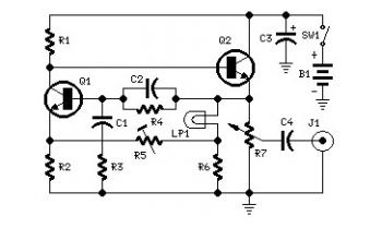
Set R5 to read 1V RMS on an audio millivoltmeter connected to the output with R7 rotated fully clockwise, or to view a sine wave of 2.828V peak-to-peak amplitude on the oscilloscope. An audio amplifier is an electronic device...
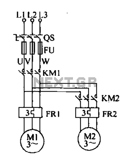
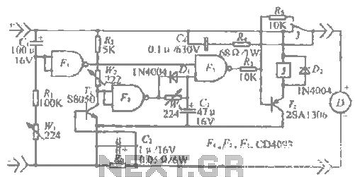
Delay starting a motor control circuit The motor control circuit designed for delayed activation incorporates a timing mechanism that ensures the motor does not start immediately upon receiving power. This is particularly useful in applications where a staggered startup...
This is a component of a 100W RF amplifier. This circuit is constructed using the RF power transistor BLY94. Components include the BLY94 transistor, inductor, and others. The 100W RF amplifier circuit utilizing the BLY94 transistor is designed to amplify...
The "R-h sampling circuit limit order" aims to reduce the sampling resistor. A DC voltage level can be positioned between the components. The circuit includes a line amplifier that allows for magnification adjustments and is designed to protect against...
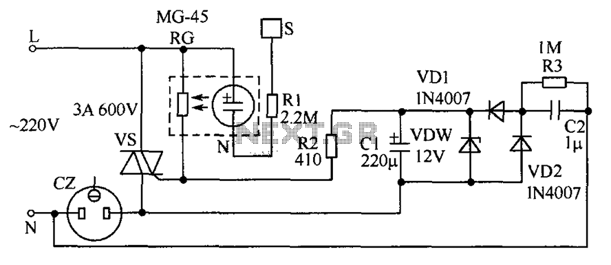
The circuit operates by detecting a finger touch on a metal sheet (S), which activates a neon tube light (N). The combination of the neon tube and a photoresistor (RG) acts as an optocoupler, reducing the resistance of RG....
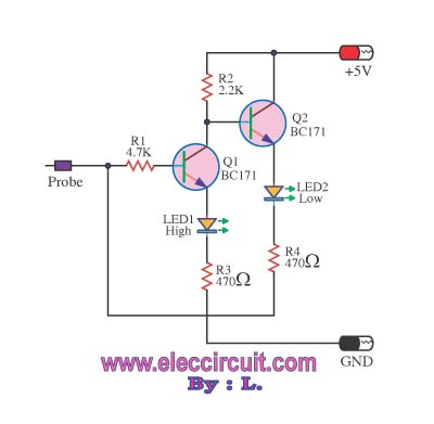
This logic probe circuit is designed for checking voltage levels in TTL circuits. It receives signals from the circuit being tested and indicates whether the logic level is high or low. When the input voltage at the probe tip...