
Micropower thermometer
This circuit is designed to provide a reliable and efficient method for temperature measurement and monitoring. The use of a current output rather than a voltage output is particularly beneficial in applications where long transmission lines are involved, as it minimizes the effects of resistance and noise that can affect voltage signals. The low duty cycle operation significantly reduces power consumption, making this circuit suitable for battery-powered applications, such as in remote sensing or portable devices.
The temperature sensor used in this circuit should have a linear response to temperature changes to ensure that the output current accurately reflects the temperature being measured. The choice of operational amplifier or resistor for converting the current to a voltage output should be based on the specific requirements of the application, including the desired output range and the input impedance of any subsequent circuitry.
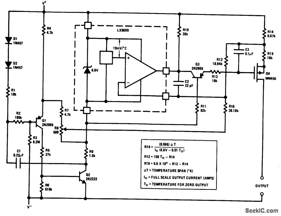
The trimming resistor R8 plays a crucial role in ensuring the accuracy of the circuit by compensating for variations in component tolerances. This adjustment allows for precise calibration of the output current in response to temperature changes. The specified output range of 0 to 50 µA for a temperature change of +50 to +100 °F can be adjusted by selecting appropriate resistor values in the circuit, as indicated in the accompanying equations.
Overall, this circuit is an effective solution for applications requiring precise temperature measurement with minimal power consumption, making it suitable for a wide range of electronic and industrial applications.The output of this circuit is a current proportional to temperature, which can be used to drive a meter for a direct readout. Alternatively, a resistor or op amp can be used to get a voltage output. The circuit is pulsed at a low duty cycle to reduce power consumption. With the component shown, the duty cycle is about 0. 2% with a one-se cond sample rate. This gives an average current drain of about 25 A, plus the output current. The circuit will operate with a supply of 8. 0 to 12. 0 V. A small 8. 4-V mercury battery can provide an operating life of about one year. R8 is used to trim the circuit, correct for Zener tolerance, temperature error in the sensor, and resistor tolerance. With the values shown, a 0- to 50- A output is obtained for a +50 to + 100 °F temperature change. Other ranges can be selected using the equations shown in the box on the circuit diagram. The current-source output allows long lines to be driven with no loss of accuracy. National Semiconductor Linear Applications Habdbook, 1991, p. 1229. 🔗 External reference
Related Circuits

Using a J-type thermocouple, this circuit can indicate temperatures from -350° to 400° with a 6-V supply or from -50° to +100° with a 3-V lithium battery. The AD954 produces a 10 mV/°C output to the MAX 138 digital...
The receiver circuit and display module will receive the high-frequency AC power cord and decode it to provide actual temperature readings using digital IC No. CD4553 (Three-digit BCD Counter IC) and IC CD4511 (BCD-to-7-Segment Latch/Decoder/Driver IC). The frequency pulses...

Ceramic resonators are suitable for low-power, low-frequency clock sources, despite their 30-ppm temperature coefficient. However, they exhibit troublesome spurious-resonance modes. This circuit effectively rejects all but the fundamental mode of the resonator. The clock circuit operates within a temperature...
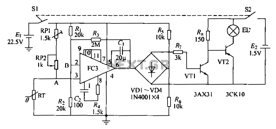
The circuit diagram illustrates an electronic thermometer. RT represents the thermistor, while A denotes an integrated operational amplifier. The diodes VD1 to VD4 provide a unidirectional output signal. The transistors VT1 and VT2 form a switching circuit. When the...
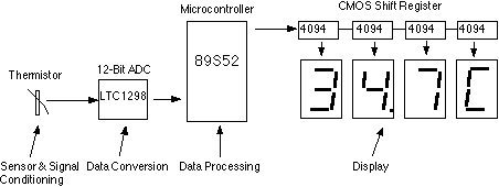
This assignment pertains to the course "Designing Microprocessor Based Instrumentation." The project features a board that utilizes a 12-bit ADC, a C program with digital filtering, and an LED display interface. It achieves a temperature reading sensitivity of 0.1°C....

Compared to other operational amplifiers, the OP90 has a significant advantage in low power consumption. Its low power requirements allow for a wide range of power supply voltages (from 1.6V to 18V, and it can also operate with dual...