
Applications of SR Drive Systems on Electric Vehicles

The electric vehicle drive system encompasses several critical components that work in unison to optimize performance and efficiency. The switched reluctance motor (SRM) is designed with a robust rotor structure that enhances stability and durability under varying operational conditions. Its high reliability is attributed to the absence of permanent magnets, which mitigates issues related to temperature-induced demagnetization. The SRM's construction allows for effective torque generation and management, making it an ideal candidate for electric vehicle applications.
The control strategies implemented for managing torque fluctuations are essential for ensuring smooth operation and enhancing vehicle responsiveness. Techniques such as fuzzy logic adaptive control are employed to dynamically adjust the torque output based on real-time feedback, thus improving overall drive quality. The incorporation of full rotor pitched insulating non-magnetic colloid techniques further minimizes electrical losses and enhances the motor's performance.
Noise reduction is another critical aspect of electric vehicle design. By categorizing noise sources and implementing targeted solutions, such as optimized rotor designs and advanced materials, the overall acoustic signature of the vehicle can be significantly reduced. This not only improves passenger comfort but also meets regulatory noise standards.
In terms of power matching, the vehicle dynamics model plays a vital role in determining the optimal specifications for the motor and drive system. By analyzing the forces acting on the vehicle, such as rolling resistance, gradient resistance, and aerodynamic drag, engineers can ensure that the motor is appropriately sized to meet performance requirements without compromising efficiency. This model allows for the fine-tuning of motor parameters to achieve the best balance between power output and energy consumption, ultimately leading to a more sustainable electric vehicle solution.As the continuous growth of global vehicle production and owned, the problems brought by vehicles are conspicuousness day after day. These problems are much more serious in China. Thus developing zero emission electric vehicles have become the main scientific research projects in many countries around the world in 21st century.
Energy-saving motor drive technology has become one of the key points to the EV commercialization. In the present electric vehicles, there are several main drive systems include the chopping system of DC motor, the variable frequency drive system of induction motor(IM), the drive system of permanent-magnet motor(PM) and switched reluctance drive system(SRM), etc. The DC machine has been faded gradually in the electric vehicle drive system for the reason of high startup current, huge volume, low efficiency and poor reliability.
Even worse, the carbon body and the commutator which are not suited for high speed movement need to be changed frequently. The variable frequency drive system of IM has a small torque fluctuation, but with low efficiency especially in the low speed stage.
When the electric vehicle is grade climbing, the torque output is small and the current is high. Although the permanent-magnet motor is of high efficiency, the manufacturing technique is very complicated and the machine will lose effectiveness because of the demagnetization in high temperature. So it is not the perfect way. The structure of the SR Motor is firmly and stable. The SRD system has a high reliability, wide range of speed regulation, high efficiency, low startup current and large torque output, all of which are especially suited for the work condition of the electric vehicles.
The application of SRD on electric vehicles is affected by the torque fluctuation and strong noise. In a word, performance comparisons of the three motors are indicated in the following table 1. Many control different strategies have been proposed for the torque fluctuation task. Full rotor pitched insulating non-magnetic colloid techniques of SRM and SRM fuzzy logic adaptive torque control system based on instantaneous torque sum are proposed in this chapter. The noise sources can be divided into four broad categories: magnetic, mechanical, aerodynamic and electronic.
Therefore, according to the magnetic flux in the machine passing across the air gap in an approximate radial direction producing radial forces on the stator and rotor result in magnetic noise and vibrations, selection of 12/8 construction is used in the SRM design and a new rotor structure is proposed in this section. The selection of driving motor on electric vehicles mainly depends on rated power and rated speed. The more power grade is choosed the more reserve-power is got and the better vehicle driving feature is.
But the volume and weight of the motor will increase rapidly by the same time and lead to the decline of the motor efficiency. So, the motor power should not too large. The calculation of power matching of EV motor is as follows: A simplified model of the road vehicle dynamics can be used to estimate the tractive requirement of the vehicle drive-train, from which the individual component specifications can be rated with-regard-to their peak and continuous duties.
The vehicle model accounts for the resultant forces acting against the vehicle when starting and when in motion, as illustrated in following figure 1. These forces can generally be considered as comprising of four main components, viz. : Where the force to overcome the tyre to road power loss, or rolling resistance, Fr = krmgcos, a resistive force related to the road gradient, F w =mgsin, an aerodynamic resistance or drag force, Fa=1/2 C d A f v 2, and
🔗 External reference
Related Circuits
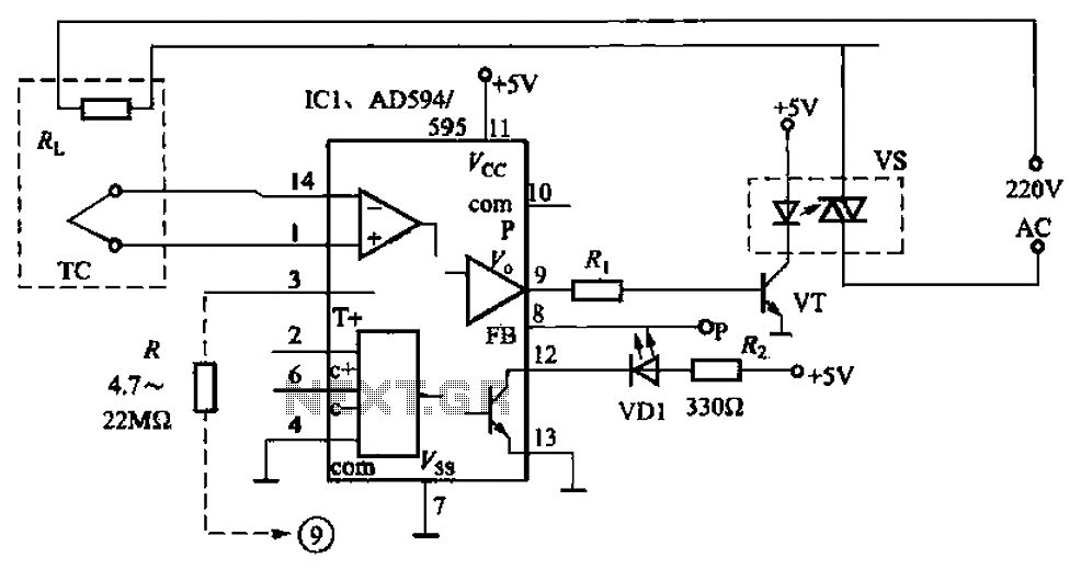
An automatic electric furnace temperature controller is depicted in FIG. 1-25. The closed circuit is established through a temperature detection output control loop. As the temperature rises, the output voltage increases. When the voltage reaches a preset temperature value,...
This is a status panel driver circuit. This circuit is used to turn on lamps or LEDs in a graphic panel that represent faults, actions, and the status of an application. The status panel driver circuit is designed to control...

I have attempted to create drivers for my H-bridge circuit using complementary emitters; however, the square wave outputs consistently run at a constant 25V instead of a ±10V square wave. The image is somewhat difficult to interpret, but it...
Whenever there is a need for battery-powered lighting, such as for camping, solar-powered cottages, cars, boats, planes, or emergency situations, fluorescent lamps are highly appealing. They are significantly more efficient than incandescent lamps, producing much more light for less...
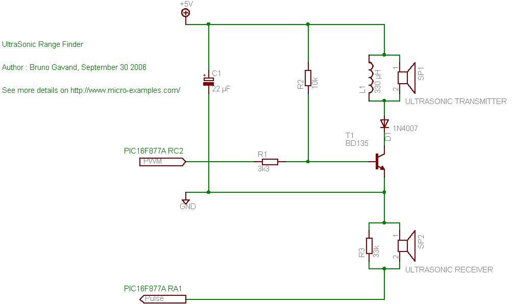
A cat deterrent system utilizing an Arduino, similar to existing models. Detection has been successfully implemented, and it has been determined that an ultrasonic transducer is required to generate the necessary deterrent sound. The proposed cat deterrent system employs an...
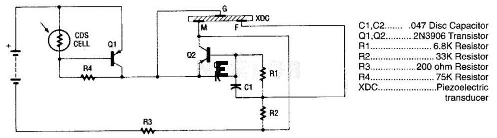
The alarm utilizes a fixed-frequency piezoelectric buzzer alongside a cadmium-sulfide (CDS) cell and a two-transistor circuit to create a distinctive effect. When light reaches the CDS photoelectric cell, the alarm remains silent. However, in the absence of light, transistor...