
Microprocessor programmable interval timer
At the conclusion of the programmed time interval, an interrupt one-shot is activated, signaling the microprocessor that the designated time has elapsed. By utilizing a resistor of approximately 10 ohms and a capacitor of 0.1 µF, the ICM7240 establishes a time base of one second. Consequently, the microprocessor can program time intervals ranging from 1 to 255 seconds, with the ability to adjust either R or C to select longer or shorter time bases.
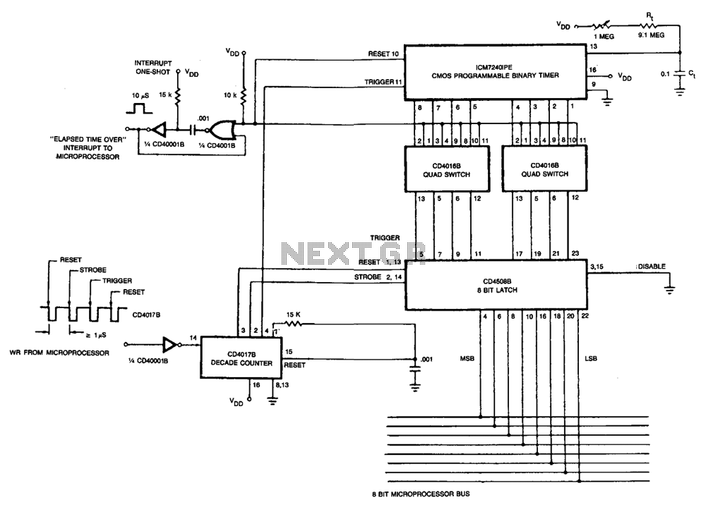
The described circuit utilizes a microprocessor to control an ICM7240 timer, interfacing through an 8-bit I/O bus. The microprocessor sends an 8-bit binary code that configures the timer, which is essential for timing applications. The CD4017B decade counter is employed to manage the timing operations through a series of WRITE pulses. The first pulse is crucial for resetting the 8-bit latch, ensuring that any previously stored data does not interfere with new inputs. The second pulse is responsible for transferring the binary code into the latch, effectively programming the timer with the desired count.
The third pulse is significant as it triggers the ICM7240 to commence its timing cycle, initiating the measurement of the time interval based on the external resistor-capacitor (R-C) configuration connected to pin 13. This configuration determines the duration of the timing cycle, which can be adjusted to meet specific application requirements. The fourth pulse resets the CD4017B counter, preparing it for subsequent operations.
Once the programmed time interval elapses, the interrupt one-shot is activated, which serves as a notification mechanism to the microprocessor, indicating that the timing cycle has completed. This feature allows the microprocessor to undertake further actions based on the elapsed time.
The choice of a 10-ohm resistor and a 0.1 µF capacitor establishes a one-second time base for the ICM7240. This configuration allows for programming time intervals that can be varied from 1 to 255 seconds, providing flexibility in timing applications. Adjustments to the R or C values enable the selection of different time bases, facilitating a wide range of timing scenarios suitable for various electronic applications.The microprocessor sends out an 8-bit binary code on its 8-bit I/O bus (the binary value needed to program the ICM7240), followed by four WRITE pulses into the CD4017B decade counter. The first pulse resets the 8-bit latch, the second strobes the binary value into the 8-bit latch, the third triggers the ICM7240 to begin its timing cycle and the fourth resets the decade counter.
The ICM7240 then counts the interval of time determined by the R-C value on pin 13, and the programmed binary count on pins 1 through 8. At the end of the programmed time interval, the interrupt one-shot is triggered, informing the microprocessor that the programmed time interval is over. With a resistor of approximately 10 ohm and a can capacitor of 0.1 µ¥, the time base of the ICM7240 is one second.
Thus, a time of 1-255 seconds can be programmed by the microprocessor, and by varying R or C, longer or shorter time bases can be selected. 🔗 External reference
Related Circuits
This circuit is designed to power a lamp or other appliance for a specified duration of 30 minutes, after which it automatically turns off. It is particularly useful for nighttime reading, as it can turn off a bedside lamp...
This timer was designed for people wanting to get tanned but at the same time wishing to avoid an excessive exposure to sunlight. A Rotary Switch sets the timer according to six classified Photo-types. A Photo resistor extends the...
Twelve LEDs can be arranged in a circle to represent the twelve hours of a clock face, while an additional twelve LEDs can be arranged in an outer circle to indicate five-minute intervals within the hour. Four additional LEDs...
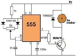
This project utilizes a 555 timer to control the speed of a 6-volt DC motor. Speed adjustment is achieved by rotating a 50 kΩ potentiometer either to the left or right. The circuit employs the 555 timer in astable mode,...
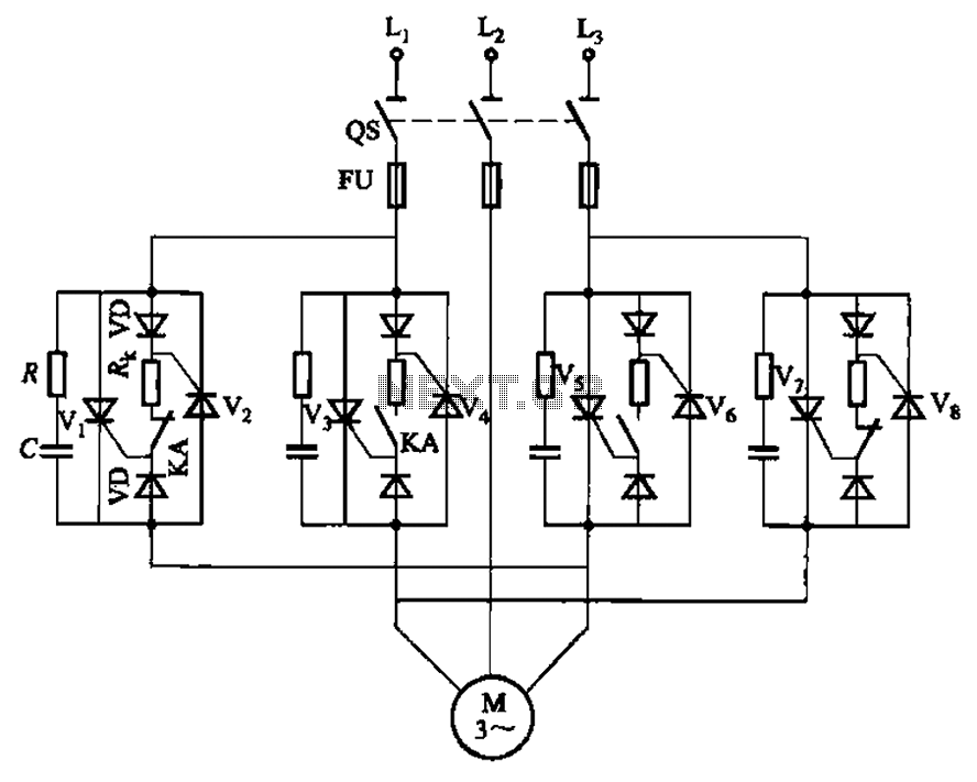
The circuit depicted in Figure 3-69 is designed for applications requiring frequent timing control for motor reversing operations. In this configuration, thyristors V1, V2, V7, and V5 are utilized for positive control of rotation, while thyristors V3, V4, and...
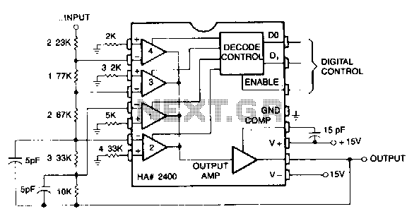
This circuit can be programmed for a gain of 0, -1, -2, -4, or -8. This could also be accomplished with one input resistor and one feedback resistor per channel in the conventional manner, but this would require eight...