
dc motor driver with h bridge ic l293d
The L298 motor driver is a robust solution for driving DC motors in various applications, offering versatility in controlling motor direction and speed. The dual H-Bridge configuration allows independent control of two motors, making it an ideal choice for robotics and automation systems. Each H-Bridge can handle a maximum continuous current of 2A, providing sufficient power for small to medium-sized DC motors.
When operating in parallel mode, two L298 driver ICs can be connected to effectively double the output current capacity to 4A. This setup is particularly useful for applications requiring higher torque or when driving larger motors. The configuration requires careful attention to the thermal management of the circuit, as increased current can lead to higher temperature rise in the driver ICs. Adequate heat sinking or thermal dissipation methods should be employed to maintain reliable operation.
The absence of internal flyback diodes necessitates the addition of external diodes to prevent back EMF generated by the motors from damaging the driver. Flyback diodes should be selected based on the maximum current the motors will draw and should be connected in reverse bias across the motor terminals. This addition ensures that any inductive kickback is safely redirected, protecting the driver and maintaining circuit integrity.
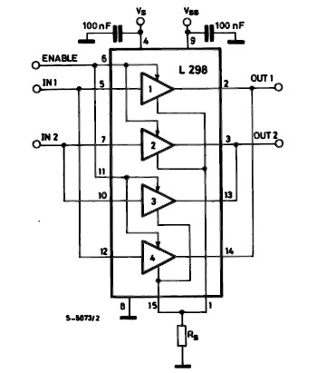
Overall, the L298 H-Bridge DC motor driver is a versatile component that, when properly configured with additional protective measures, can efficiently control multiple DC motors in a variety of applications. Its capability to handle significant current loads while providing directional control makes it a popular choice among engineers and hobbyists alike.IC H Bridge DC motor driver L298 has two H-Bridge circuit in it, so it can be used to download the drive two DC motors. H Bridge DC motor driver L298 each can deliver currents up to 2A. However, in use, the H Bridge DC motor driver L298 can be used in parallel, so the ability to deliver the H Bridge DC motor driver L298 flow into 4A.
The consequences of the installation of H Bridge L298 DC motor driver with the parallel mode, you need 2 pieces Bridge H L298 DC motor driver to control two DC motors using H bridge DC motor driver L298 in parallel mode. Please note that the output of the L298 does not have a safety diode. Thus, the need to add two diodes - flyback diodes, with appropriate current capability, at any point output.
🔗 External reference
Related Circuits
Two inputs, A and B, control the bridge. With both high (or open circuit) both ends of the motor are connected to 0v. Connect A low and Tr2 turns on causing the motor to go forward. Connect B low...
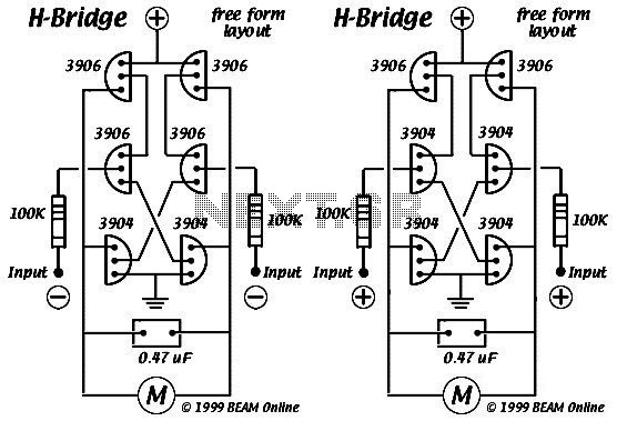
This diagram illustrates the 6 transistor Tilden H-bridge circuit. Although it is not as old as the original basic H-bridge, it has a long history and serves as the foundation for many BEAM driver circuits. Bruce Robinson provides an...
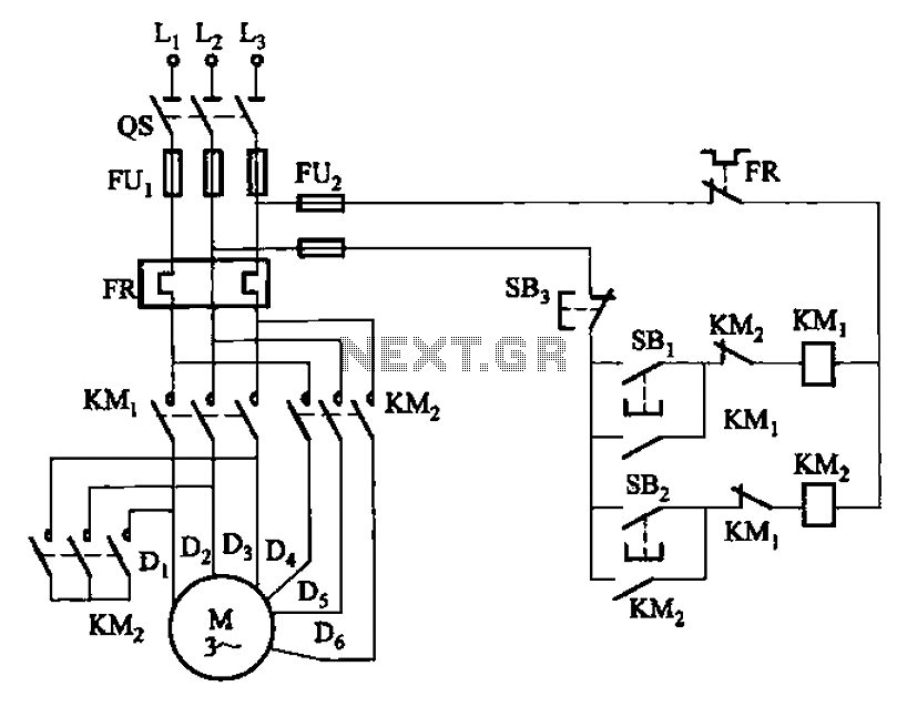
The circuit illustrated in Figure 3-97 features two contacts and is designed specifically for a 2kW dual-speed motor. In this configuration, SB1 is utilized for low-speed operation, while SB2 serves as the high-speed run button. The circuit operates by allowing...
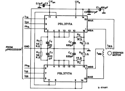
The PBL3717A stepper motor driver is a monolithic integrated circuit that controls and drives one phase of a bipolar stepper motor utilizing chopper control for phase current regulation. Current levels can be selected in three increments using two logic...
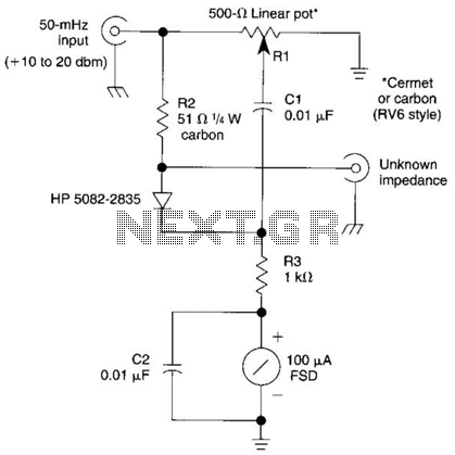
The bridge shown was used for measurements on 50-MHz amateur radio antennas. Rl is a miniature 500 linear potentiometer. The unknown impedance is compared to R2, a 51-ohm resistor. An external signal source is required. The described bridge circuit is...
This involves controlling servo motors through software programming using the PIC 16C71 microcontroller. The input signals range from 0 to 5V. The circuit utilizes the PIC 16C71 microcontroller, which is an 8-bit device suitable for controlling servo motors. The microcontroller...