
PLL Oscillator for Medium Wave Frequency

A phase-locked loop (PLL) oscillator is a sophisticated electronic circuit designed to synchronize an output signal's phase and frequency with that of a reference signal. The primary components of a PLL include a phase detector, a low-pass filter, and a voltage-controlled oscillator (VCO).
The operation of a PLL begins with the phase detector, which compares the phase of the input reference signal to the phase of the output signal from the VCO. The phase detector generates a voltage output proportional to the phase difference between these two signals. This voltage is then fed into a low-pass filter, which smooths out the rapid variations in the signal, producing a steady control voltage that adjusts the frequency of the VCO.
The VCO generates an output signal whose frequency can be varied by the control voltage provided by the low-pass filter. As the VCO adjusts its output frequency, the phase detector continuously monitors the phase relationship between the reference signal and the VCO output. The PLL will maintain lock as long as the phase difference remains within a specified limit, effectively ensuring that the output signal remains synchronized with the reference signal.
PLLs are widely used in various applications, including radio, telecommunications, and clock generation in digital circuits. They are essential for frequency synthesis, demodulation, and data recovery, making them a fundamental building block in modern electronic systems.What is a PLL oscillator? PLL stands for phase locked loop, and this means a control method by comparation of the controlled plant or system to a reference.. 🔗 External reference
Related Circuits
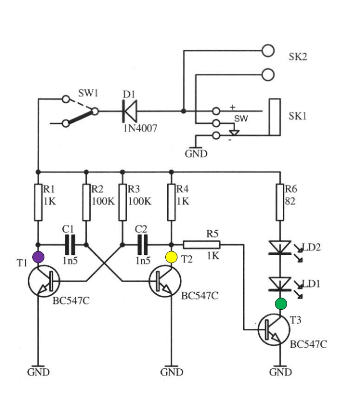
The schematic circuit presented below illustrates an infrared transmitter. The infrared beam is emitted in a nearly line-of-sight manner towards another device equipped with an infrared receiver. The displayed waveforms represent the output voltages from two intermediate stages (purple...
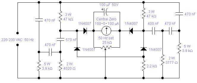
Mains frequency is pretty stable and it is unlikely that you have to measure it but if you have an emergency generator you might find this circuit useful as it will give an indication whether the generator is running...
Hartley oscillators are inductively coupled, variable frequency oscillators that can be series or shunt fed. They feature a center-tapped inductor and a tuning capacitor, which simplifies the circuit construction. The schematic includes a buffer stage and an amplifier stage...
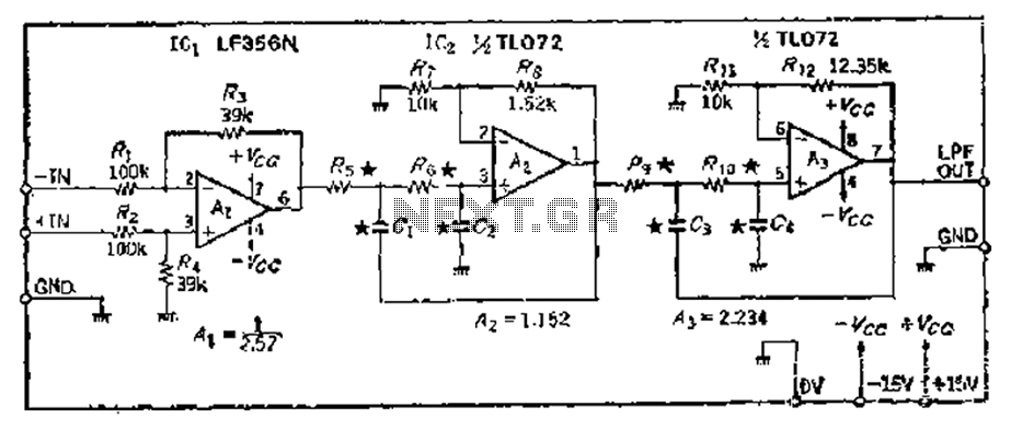
A 24 dB/octave Butterworth filter with a maximally flat characteristic is constructed using two filters, each capable of providing a 12 dB/octave response. This configuration allows for a 3 dB point adjustment. To achieve the desired cutoff frequency, adjustments...
This circuit generates a stable 1 kHz sine wave using an inverted Wien bridge configuration composed of components C1, R3, C2, and R4. It features a variable output, low distortion, and low output impedance to ensure good overload capability....
A basic square wave generator has been designed to operate a speedometer circuit board, which is responsible for controlling various functions. The square wave generator circuit typically consists of a few key components: a timer IC, such as the 555...