
MIDI Sync Box
The circuit design incorporates a PIC microcontroller that serves as the central control unit, responsible for managing multiple functionalities including LED driving, MIDI output, and input reading through multiplexing. The choice of a PIC microcontroller allows for efficient processing and control due to its integrated timer and I/O capabilities. The use of multiplexing enables the microcontroller to manage the seven-segment display while simultaneously reading multiple inputs, optimizing the use of available I/O pins.
The MIDI output is configured to operate based on current rather than voltage, which necessitates careful consideration of the output configuration. Connecting pin 4 of the DIN connector to 5V and pin 5 to the microcontroller output creates an inverter setup, allowing for compatibility with standard logic levels. This configuration ensures that the microcontroller can effectively communicate MIDI signals, which are characterized by their unique start, stop, and data bit arrangements.
The integration of a rotary encoder as a control input enhances the system's usability, providing precise feedback and eliminating the inaccuracies associated with potentiometer-based voltage readings. The rotary encoder's binary counting mechanism, combined with its detent feature, allows for reliable and consistent input, making it an ideal choice for applications requiring precise adjustments.
The firmware development process continues to evolve, with ongoing revisions and improvements being made to enhance functionality and performance. The complexity of the software, along with the challenges encountered in understanding and implementing MIDI communication protocols, reflects the intricate nature of electronic design and programming. Overall, the project demonstrates a successful integration of hardware and software components, resulting in a robust and efficient electronic system.Everything works just great. The final software is 930 lines of assembler. I also learnt how to use ProTel so I could draw up the final circuit properly. Here`s the result. Notice that I`ve got it down to just one chip now, the little PIC is doing everything. It can directly drive the LED and the MIDI output. I`ve used multiplexing to enable it to drive the 7 segment display and read all the inputs. The PIC`s built in timer keeps everything running accurately, all in all, I`m very pleased with the result. Since I last did any work on this project, I have upgraded my PC to a Duron 900 and have installed Windows 2000. I am most impressed with the stability of Win2K, I rarely have more than two crashes per week as opposed to about three times a day under Win98.
However, Windows 2000 will not run the NOPPP software which I have been using to download code into the PIC. I suspect the way ports are accessed in Win2K is not backward compatible with Win95. To cut a long story short, I have found the Linux version of NOPPP works just fine so I`m using that instead.
gpasm is a free compiler for the PIC which runs on Linux so I`m all set to continue development without using Windows. I`ve redesigned the thing again and got rid of the buffer chip. I`m driving the MIDI output directly from the PIC and it works fine. I`ve used a 7 bit bus arrangement to allow all the inputs to share the same I/O pins as the LED display.
One little hitch was the discovery that the big red illuminated push button needs 12 volts to light up. But I`m running everything off 5 volts. So I`ve made a little adapter out of a small piece of veroboard so I can substitute a LED. I tellya these modern LEDs are so bright! I nearly blinded myself messing about with it. One thing I had a lot of trouble with was understanding the MIDI signals. I couldn`t seem to find much documentation on them. I had to do a lot of trial-and-error and also use my CRO to analyse the signals coming out of some MIDI equipment.
Here`s what I found: MIDI works by current, not voltage. The receiving end has a 1k input impedance and the sender is expected to put a 5V voltage differential across this which produces a current of 5mA. Current flow is indicative of a logic 0. No current flow is a logic 1. There is no current flow when the line is idle. A fairly standard way to implement a MIDI output is to tie pin 4 of the DIN plug to 5V and pin 5 to your digital output.
This forms a hardware inverter so you can use normal logic levels in your circuit. Another confusing thing is that nowhere is it described how the serial data is sent. The literature will tell you that there is 1 start bit, 8 data bits and one stop bit. Great, just like RS-232 I thought. Well no, it`s not anything like RS-232. The start bit in MIDI is a 0, the stop bit is a 1 and the data bits are sent in reverse order. All perfectly fine but I had to discover this myself. I`m steadily building the firmware for this thing. Something that sounds simple is turning out to be a little more complex than I thought, still, that`s pretty normal in the software world. My program is around 600 lines and I`ve still got a lot of stuff left to do. Another problem I`ve come across is the Potentiometer voltage ramp arrangement has turned out to be not very accurate, the reading varies wildly depending on voltage, temperature, current and just about any other variable you can think of.
After wasting a lot of time with it, I`ve decided it`s just not a suitable method for setting the speed. So instead, I`ve got myself a rotary encoder. This looks like a potentiometer but it`s actually a binary counter which increments as you turn it. It has detents so it won`t drift once you turn it to a specific position and is generally much more suitable for this role.
Now it`s time to move back i 🔗 External reference
Related Circuits
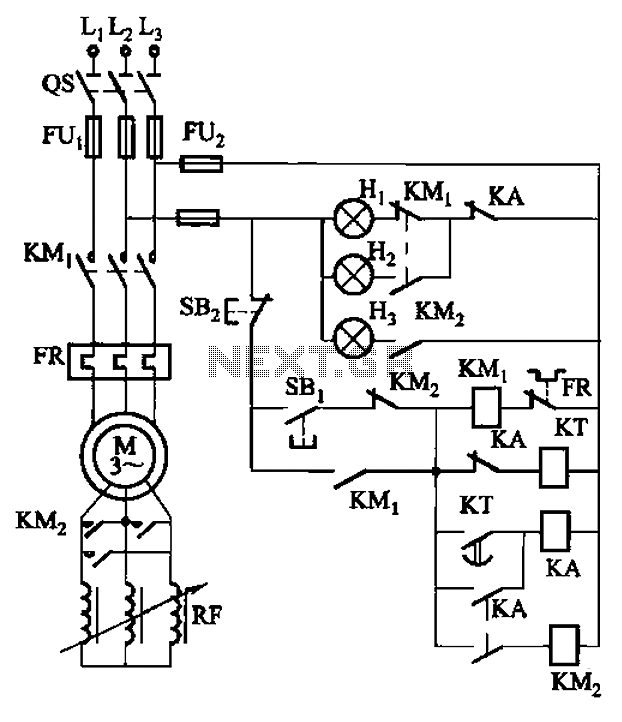
The circuit depicted in Figure 3-165 utilizes a time relay (KT) for controlling the start-up time. Indicator light Hi serves as the power indicator, H2 is designated for the start lights, and H3 functions as the running lights. The circuit...
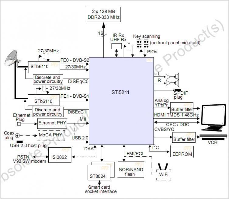
The STI7167 utilizes advanced process technology to deliver a fully featured HD AVC DVB-C and DVB-T demodulator and decoder integrated circuit (IC). This highly integrated system-on-chip is designed for set-top box (STB) markets across cable, terrestrial, and terrestrial/IP hybrid...
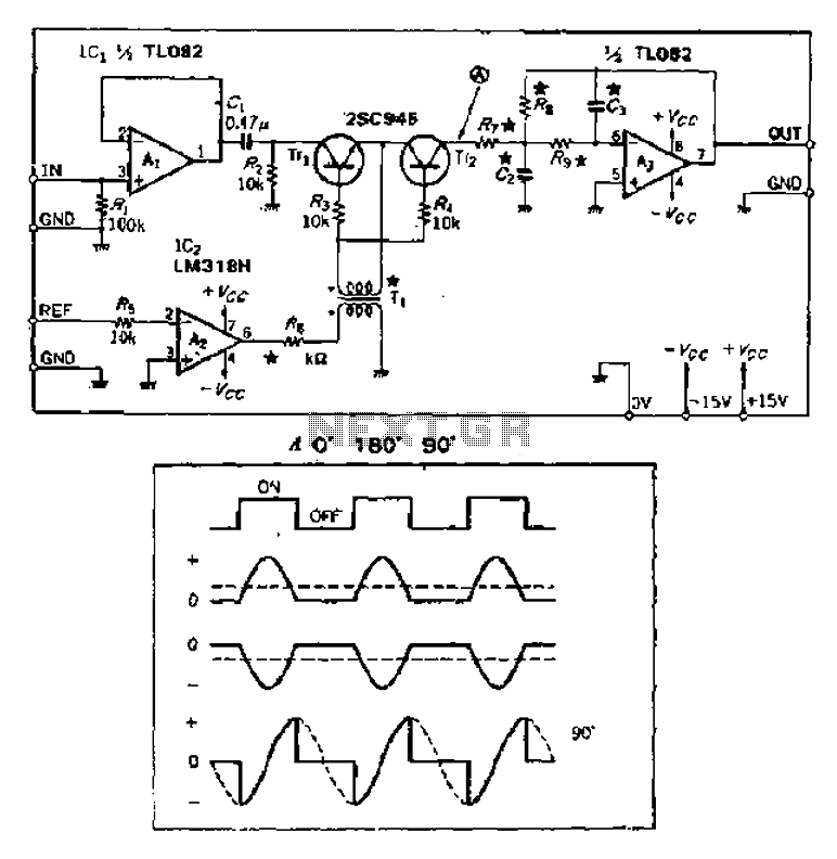
Analog switches alternately pass and block the input signal through a low-pass filter to create a pulsating flow smoothing effect, converting it into a direct current (DC) signal. The operational amplifier, referred to as OP Xiao Ai, functions as...
The circuit employs an astable multivibrator to alternate between heads and tails conditions, while a flip-flop is utilized to retain the state determined by the multivibrator. As a result, the circuit is designed so that the flip-flop's state changes...
In certain video applications, signal sources provide RGB signals along with a composite sync signal. The RGB signals do not include video sync. On the receiving end, some budget video decoders lack a separate composite sync input; they only...
The ADF4107 Frequency Synthesizer can be used to implement local oscillators in the upconversion and downconversion sections of wireless receivers and transmitters. It consists of a low noise digital phase frequency detector (PFD), a precision charge pump, a programmable...