
Toss-a-coin binary box

The described circuit consists of two main components: the astable multivibrator and the flip-flop. The astable multivibrator is configured to generate a continuous square wave output, oscillating between high and low states. This output is responsible for determining the alternating heads or tails condition. The frequency of the multivibrator can be adjusted using resistors and capacitors, allowing for control over the rate at which the heads or tails condition changes.
The flip-flop serves as a memory element, capturing the output state of the astable multivibrator. Each time the multivibrator completes a full cycle, the flip-flop is triggered to change its state. This mechanism ensures that the output remains stable until the next triggering event occurs, effectively storing the current condition of heads or tails.
To achieve a 50-50 chance of either outcome, the design must ensure that the timing of the multivibrator's oscillation is consistent and reliable. The components used in the multivibrator circuit should be selected for their precision and stability, minimizing any variations that could skew the probability. Additionally, the flip-flop should be of a type that allows for clean transitions between states, reducing the likelihood of glitches during state changes.
In summary, this circuit design efficiently utilizes an astable multivibrator and a flip-flop to create a reliable mechanism for alternating between two states with equal probability. The careful selection of components and design parameters plays a crucial role in achieving the desired performance and reliability of the circuit.Circuit uses an astable multivibrator to vary the heads-or-tails condition, and a flip-flop to store the condition given by the multivibrator Consequently, the circuit is wired so that the flip-flop"s state is changed once for each full cycle the multivibrator goes through to assure an absolutely even 50-50 chance of a heads or tails loss. 🔗 External reference
Related Circuits
This device listens to conversations and then interjects words and phrases at inappropriate times. I got this box at a local thrift store for $1.50. It has a nice hinged top and a place to insert a panel with...

The schematic has been divided into three sections for improved comprehension. The first section illustrates the audio output circuit. This project is designed to output audio. The audio output circuit typically involves several key components that work together to process...
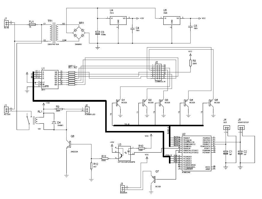
The procedure outlines the construction of a Box, Lamp System, and Countdown System utilizing the AVR Mega8 microcontroller. The system features four blacklight lamps, each rated at 15W, which emit radiation primarily in the UVA spectrum, peaking around 350nm,...
When an individual touches the safety box or other protected metal objects, the sensor circuit generates a pulse to the alarm circuit. The positive edge of this pulse activates the semiconductor and thyristor flash GE, subsequently triggering the camera...
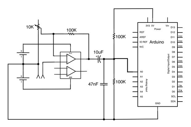
This Arduino-powered vocal effects box pitch shifts and distorts incoming audio signals to produce a wide variety of vocal effects. This project serves as an experiment with real-time digital signal processing using Arduino. It samples an incoming microphone signal...
The calculated value for the RSet resistor is approximately 17k ohms, although it should ideally be 28k ohms according to the data provided in the MV7744 datasheet, which specifies a forward voltage (Vf) of 2.1V and a forward current...