
Combining the Composite Sync to the Green Signal
The described circuit effectively addresses the integration of composite sync signals with RGB signals in video applications where low-cost decoders are used. The MAX9589, a high-speed video amplifier, plays a crucial role in this process. It not only combines the sync signal with the green channel but also ensures that the output maintains the integrity of the RGB signals. The circuit operates by accepting the RGB inputs and the composite sync signal and processing them to produce a synchronized output suitable for the video decoder.
The implementation involves connecting the green channel input and the composite sync input to the MAX9589. The device's internal architecture allows for the addition of the sync signal to the green channel without distorting the original RGB signals. The output from the MAX9589 is then fed into the video decoder, which can interpret the combined signal correctly.
This configuration is particularly advantageous in applications where space and cost are constraints, as it minimizes the need for additional components while enhancing performance. The anti-aliasing filtering capability of the MAX9589 is particularly beneficial, as it reduces potential artifacts in the video signal, leading to clearer and more stable image quality. This feature is essential in maintaining high video fidelity, especially in standard-definition applications where signal integrity is paramount.In some video applications, the signal sources deliver RGB signals and a composite sync signal. The RGB signals contain no video sync. At the receiver side, some low-cost video decoders do not have a stand-alone composite sync input; they only accept the sync signal with the video signal. Adding the sync signal onto the green channel for such an a pplication requires a "sync on green" circuit. There is a simple, low-cost way to add the composite sync onto the green channel for standard-definition video. The circuit in Figure 1 uses the MAX9589 to add the composite sync to the green channel, and generates the standard RGB signals at each output.
For example, consider a 0. 7VP-P green signal input and a 0. 3V composite SYNC signal input from the video sources that have 75 © terminations. From Figure 1 the output signal at the green channel after the MAX9589 is 1VP-P. For the 0. 7VP-P R and B input signals from the source, the output signals after the MAX9589 are 0. 7VP-P. There is an advantage to using the MAX9589 in this application. The MAX9589 can be used as an anti-aliasing filter in front of the video decoder and, thus, improves the video performance. 🔗 External reference
Related Circuits
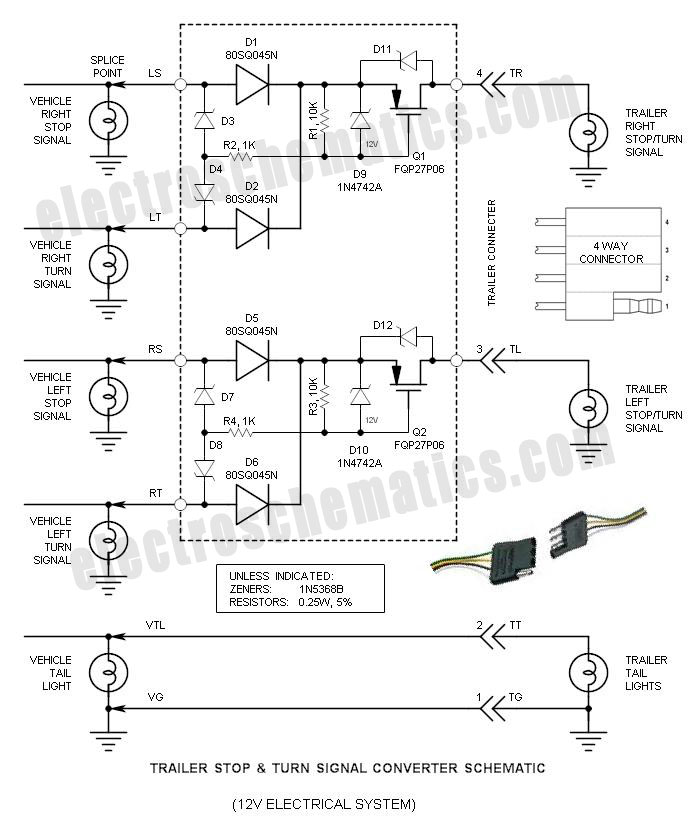
If you have ever wondered why the Stop/Turn signal lamps on your trailer appear dim, you are not alone. The reason for this is that the typical Stop & Turn Signal Converter... The dimming of trailer Stop/Turn signal lamps is...
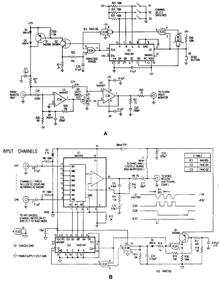
In the video system shown in Figs. A and R, a single coaxial cable transmits power to a remote location, selects one of eight video channels, and returns the chosen signal. This system can select from multiple remote surveillance...

The transition from diodes to synchronous-rectification (SR) MOSFETs in the secondary circuits of flyback converters is increasing with each new generation of MOSFETs, enhancing performance with minimal or no cost increase. SR MOSFETs can offer improved efficiency compared to...
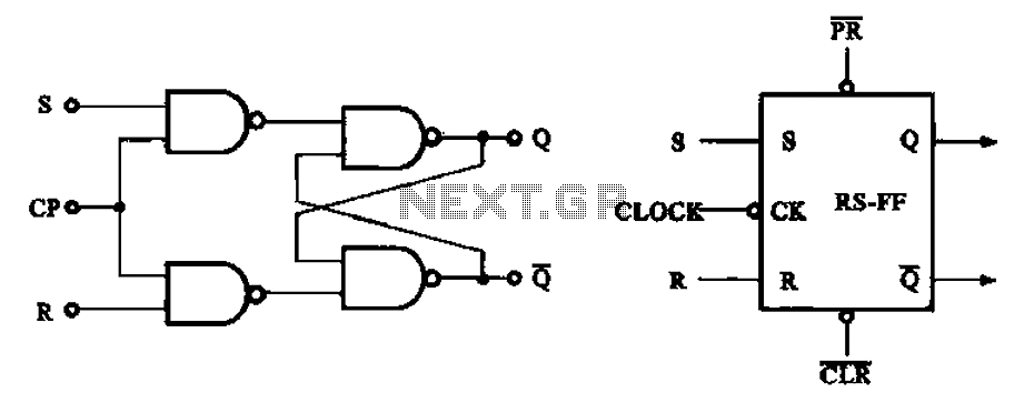
The asynchronous RS flip-flop mentioned earlier is not synchronized with the system clock signal. In contrast, the synchronous RS flip-flop incorporates synchronization, allowing it to operate in conjunction with the clock signal. Figure (a) illustrates the circuit configuration of...
.png)
The one-touch turn signal (OTTS) module enhances the functionality of the turn signal lever by introducing a mode where a single touch activates the indicators to blink for a specified number of times. This feature is commonly referred to...
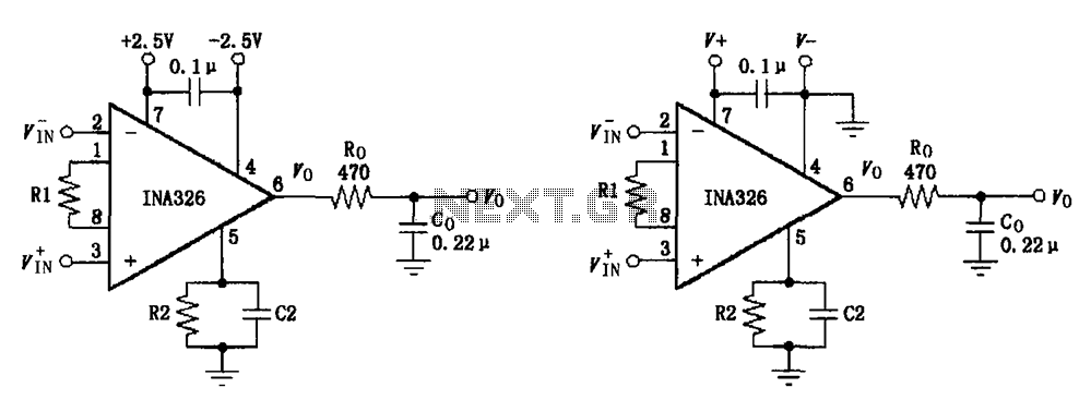
The basic connection circuit for the INA326/327 includes signals and power. A 0.1 µF capacitor is selected for power supply filtering and should be placed as close to the chip's supply pin as possible. Ro and Co serve as...