
MIDI tester circuit

The described circuit functions as a MIDI signal tester, allowing users to visually verify the transmission of MIDI data through the use of light-emitting diodes (LEDs). This device is particularly beneficial for individuals working with soundcards and MIDI interfaces, as it provides a straightforward method to confirm that MIDI signals are being sent from a computer or other MIDI-capable device.
The circuit typically consists of a MIDI connector, which is wired to an LED. The MIDI connector is generally a 5-pin DIN connector, where specific pins are designated for transmitting MIDI data. In this application, the relevant pin is the one designated for MIDI output, which sends data signals when the computer generates MIDI commands.
When the circuit is constructed, the LED is connected in such a way that it will illuminate in response to the electrical signals that represent MIDI data. The LED's flashing serves as an indicator that data is being transmitted. The brightness and frequency of the LED's flashes correspond to the intensity and frequency of the MIDI signals being sent.
To ensure proper functionality, it is crucial to adhere to the pinout configuration of the MIDI connector. The connector's pin numbers should be referenced during assembly to guarantee that the circuit is built correctly. Typically, this involves connecting the anode of the LED to the MIDI output pin while the cathode is connected to ground.
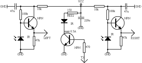
In summary, this MIDI signal tester circuit is a simple yet effective tool for verifying the operation of MIDI interfaces, making it a valuable addition to the toolkit of anyone involved in MIDI technology or soundcard development.Sometimes when experimenting with different soundcards and MIDI interfaces it is useful to see if there is some data going in MIDI interface. This can be easily tested with this adapter, which converts the midi signals to visible light pulses.
Just the circuit and plug it to the MIDI output of your computer. When computer sends any midi data out, you see the LED flashing. I found this tester very useful in testing homebuilt soundcard MIDI interface. The pinout of the connector is drawn to the picture so that they are in male connector when you look to it. The best way to make sure that you build the circuit correctly is to use the pin numbers printed to the connectors itself.
🔗 External reference
Related Circuits

This liquid detector circuit diagram is designed using common electronic components. The liquid detector can activate an active buzzer to produce sound when a certain water level is reached. Since the water sensor and control circuit for the buzzer...
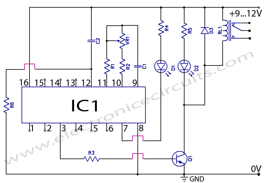
CD4060 Timer Circuit 1 minute to 2 hours This is a 1 minute to two-hour timer switch. The 14-stage binary ripple counter Type 4060, IC1, has an... The CD4060 timer circuit is designed to function as a timer switch with...
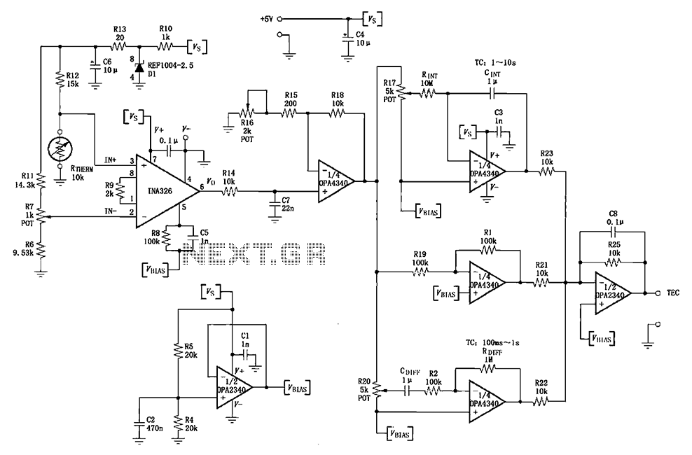
The INA326/327 forms a single power PID (proportional-integral-derivative) controller as illustrated in the temperature control loop. This circuit is primarily designed for temperature measurement and control. A thermistor, designated as RTHERM, detects temperature changes and converts them into an...
This circuit functions to monitor the duration of occupancy in a toilet, activating an alert if the time spent exceeds a predefined limit. The components involved include a resistor, integrated circuit (IC), capacitor, and transistor. The occupancy monitoring circuit is...
Create an oscillator circuit using an operational amplifier and a 7.68 MHz crystal. The design should be similar to the schematic provided below, but specifically tailored for a 7.68 MHz crystal. The available components include the crystal, various capacitors,...
The following circuit illustrates how to build a variable DC power supply circuit. This circuit is based on the 7805 IC. Features: other output is ... The variable DC power supply circuit utilizing the 7805 integrated circuit (IC) is designed...