
Midi Trigger Sequencer

The circuit described is intended to function as a programmable trigger sequencer, which allows for the generation of precise timing signals or triggers based on user-defined parameters. A typical implementation of such a sequencer involves the use of a microcontroller or digital logic components to control the timing and sequence of output pulses. The sequencer can be programmed to produce a variety of patterns, including repetitive sequences, varying pulse widths, and adjustable intervals between triggers.
To integrate an optional audio modulation stage, the circuit can include a dedicated audio processing unit that alters the output signal based on audio input or modulation parameters. This stage can utilize components such as operational amplifiers for signal conditioning, analog-to-digital converters for digital signal processing, and digital-to-analog converters to produce audio outputs. The modulation could be applied in real-time, allowing the sequencer to respond dynamically to audio signals, thus enhancing its functionality.
The schematic may include various elements such as a microcontroller with GPIO pins for trigger outputs, a clock source for timing, and potentially a user interface for programming sequences. The audio modulation stage can be designed to accept audio signals via an input jack and process them through filters or modulation effects, which can then influence the timing or characteristics of the trigger outputs.
Overall, this programmable trigger sequencer with an audio modulation stage provides a versatile tool for various applications, including music production, sound design, and experimental electronic projects. The combination of programmable triggers and audio modulation allows for creative possibilities in sequencing and sound manipulation.Add this to the above circuit to get a programmable trigger sequencer. Includes an optional audio modulation stage. 🔗 External reference
Related Circuits
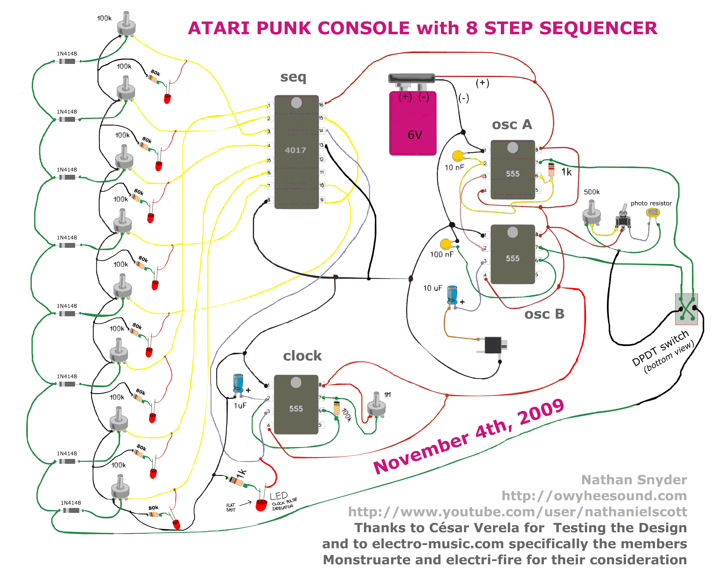
The Atari sequencer seems to have an error in its schematic. Although the Atari is operational, pressing the switch to activate the sequencer results in a loss of sound. It is suggested that pin 13 of the 4017, which...
This optical trigger is a general-purpose module designed for use with standard 3mm package infrared diode emitters and corresponding matched phototransistors. The emitter terminal on the module sources approximately 27mA to ground with a 1.2V drop across the diode....
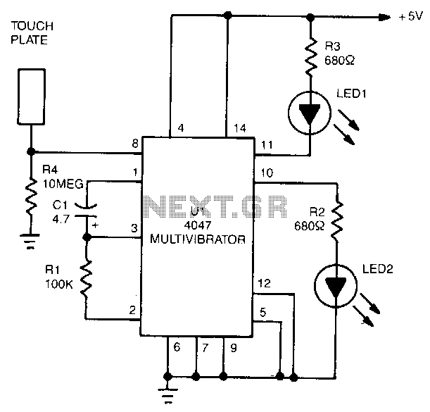
The 4047 is configured as a monostable multivibrator circuit, also known as a one-shot, which is triggered by a negative transition of the signal applied to its pin 6 input. The duration of the multivibrator's output pulse is determined...
The output current of the control circuit must be amplified when the gate current needed to trigger the device exceeds the output current of the control circuit. To achieve the amplification of the control circuit output current, a suitable transistor...

Using any camera in a dull or dark environment typically necessitates supplementary lighting. This is a common practice, even when sufficient natural light is available, to enhance contrast in conventional film photographs by using a fill-in flash for foreground...
When power is applied, the 15K resistor and 10µF capacitor at pin 15 will reset the counters to a zero count, with pin 3 at +12V and all other outputs at zero. The two diodes (1N914) and a 15Ω...