Optical Trigger Module

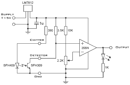
This optical trigger is a general-purpose module designed for use with standard 3mm package infrared diode emitters and corresponding matched phototransistors. The emitter terminal on the module sources approximately 27mA to ground with a 1.2V drop across the diode. The detector terminal can source a maximum of 3.4mA to ground in a short circuit condition. The circuit operates by sensing the voltage difference between the adjustable potentiometer (ADJ) level and the detector level. When there is no obstruction in the light path from the emitter to the detector, the phototransistor conducts, resulting in a low voltage at the detector terminal and a low output from the operational amplifier (op-amp). Conversely, when the light path is interrupted by an object, the conduction of the phototransistor decreases, causing the voltage at the detector terminal to rise. This generates a positive voltage difference between the op-amp inputs, resulting in a high output. The 2.2K trimmer potentiometer allows for adjustment of the triggering point to accommodate variations in the emitter-detector setup. Power is supplied via a 3mm/1/8" jack socket, with internal regulation to 12V. An LED indicates whether the output is high, which serves as a useful diagnostic feature in case of a fault in the optical gate. The component parts and assembled module are detailed below.
This optical trigger module provides a reliable means of detecting the presence or absence of an object within an infrared light path. The system is built around a straightforward operational amplifier configuration, which plays a crucial role in comparing the voltage levels from the detector terminal and the adjustable potentiometer. The phototransistor operates in a conductive state when the infrared light from the emitter reaches it unobstructed, maintaining a low voltage at the detector terminal. This low voltage condition ensures that the output of the op-amp remains low, indicating no detection.
When an object crosses the light path, the phototransistor's conduction decreases, leading to an increase in the voltage at the detector terminal. This change is detected by the op-amp, which responds by increasing its output voltage, thereby signaling the presence of the object. The adjustable potentiometer (ADJ) allows for fine-tuning of the sensitivity of the module, enabling it to be customized for different applications or varying distances between the emitter and detector.
The power supply design incorporates a 3mm/1/8" jack socket, facilitating easy integration with other systems and ensuring that the module operates at a stable 12V, thanks to its internal voltage regulation. The inclusion of an LED indicator provides immediate visual feedback regarding the output state, which is particularly beneficial for troubleshooting and ensuring the proper operation of the optical gate.
In summary, this optical trigger module is an effective solution for applications requiring non-contact detection of objects, leveraging infrared technology to achieve reliable performance. The design considerations, such as adjustable sensitivity and power regulation, enhance its versatility and usability in various electronic projects.This optical trigger is a general purpose module for use with `standard` 3mm package infrared diode emitters and corresponding matched phototransistors. The emitter terminal on the module will source about 27mA to ground with a 1. 2 V drop across the diode. The detector terminal will source a maximum of 3. 4 mA to ground (short circuit). The circuit operates by sensing the voltage difference between the potentiometer (ADJ) level and the detector level. The circuit diagram is. The circuit operates by detecting the voltage at the Detector terminal and comparing it to the preset voltage level.
When there is nothing blocking the light path from the emitter to the detector, the phototransistor is conducting and the voltage at the detector terminal is low. In this state the output from the opamp is low. When the light path is blocked by the projectile, the phototransistor conduction decreases and the voltage at the detector terminal increases.
This creates a positive difference between the opamp inputs and the output goes high. The ADJ 2. 2K trimmer pot allows some adjustment of the triggering point to accommodate variations in the emitter-detector setup. Power is supplied via a 3mm/1/8" jack socket. The supply is internally regulated at 12V. The LED indicates whether the output is high - a helpful feature if a fault occurs in the optical gate.
The component parts and assembled module are shown below. 🔗 External reference


