
MidiMotor2 Module
The circuit described involves a robust setup for handling CAN communication and motor control through H-bridge configurations. The MCP2551 serves as the interface between the CAN bus and the microcontroller, ensuring reliable signal transmission. The microcontroller's transmit and receive pins are directly connected to the MCP2551, allowing for seamless data exchange.
The quad optoisolator, U3, plays a critical role in isolating the control signals from the power side of the circuit, thus protecting sensitive components from high voltage or noise. The use of current-limiting resistors R5 to R7 is essential to prevent excessive current from damaging the optoisolator inputs.
The dual L298 H-bridges (U1 and U2) are configured to operate in tandem, effectively doubling the current handling capacity for driving motors or other inductive loads. This configuration is particularly useful in applications requiring significant power, as it allows for efficient control of motor direction and speed.
The implementation of Schottky diodes (D1-D8) is a prudent design choice, as these diodes provide fast recovery times and low forward voltage drops, thereby enhancing the reliability of the circuit during switching events. This protection mechanism is vital in preventing damage from voltage transients that can occur in inductive loads.
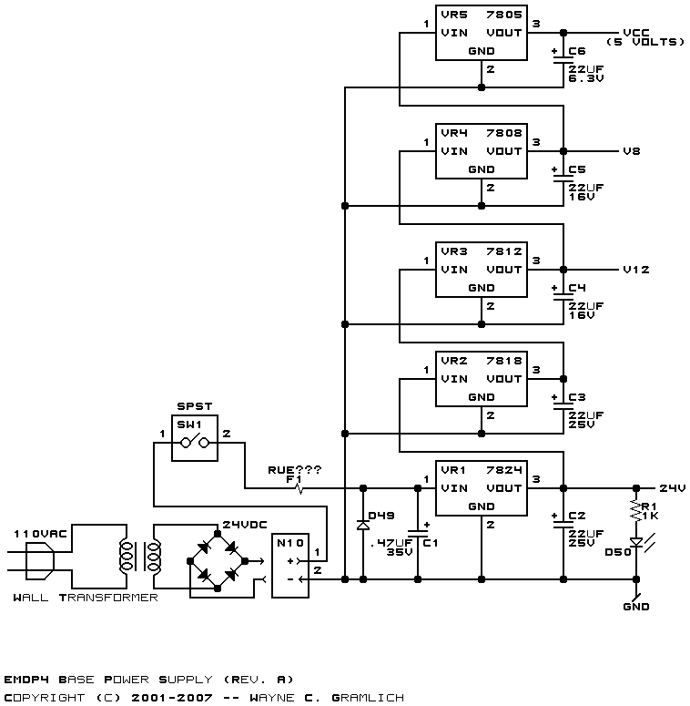
Overall, the described circuit architecture provides a comprehensive solution for integrating CAN communication with motor control, emphasizing isolation, protection, and efficient power management.The logic power and CAN signals come in from N4 pins 3 through 8. The CAN signals are connected to the MCP2551 CAN physical layer IC, U5. The transmit and receive pins of the microctroller, (U4 pins 5 and 6) are connected to the other side of U5. Lastly, the RC0 through RC3 are used to drive the quad optoislator, U3, through current limiting resis
tors R5 through R7. Please note that U3 optoisolator shows up in both schematics. There is only one optoisolator, it is just easier to understand what is going on if the optoisolator is present in both schematics. There is no shared ground between the two sides of the optoisolator. Each L298 (U1 and U2) is a dual H-bridge in a Multiwatt-15 package. As per recommended practice, the two H-bridges are ganged together to form a single H-bridge with 3. 5 Amp capacity. Power comes in on N3. The dedicated regulator VR1 provides 5 volts for the logic ciruitry. The H-bridge circuitry is always enabled. The Schottky diodes (D1-D8) are used to clamp out unwanted voltage spikes that occur as a result of switching.
Each H-bridge is connected to two optoisolators in U3 to allow independent switching of the H-bridge. 🔗 External reference
Related Circuits
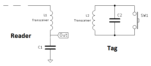
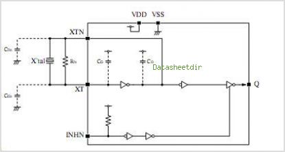
A coil of approximately 1 mH is utilized for both sides of the circuit. Given a chosen frequency of 125 kHz, the required capacitor value is calculated to be 1.62 nF, with a standard value of 1.5 nF selected....
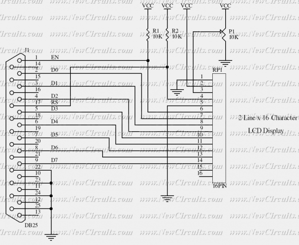
This simple circuit controls a popular 2-line x 16-character LCD by a PC via printer port. It doesn't use the Bi-directional feature found on newer printer ports, thus it should work with most, if not all, Parallel Ports. These...
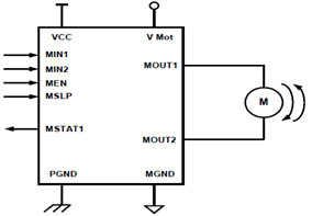
The schematic presented illustrates a 5A H-Bridge Module designed for the operation of a single Bipolar DC motor. The H-Bridge Module includes a header set (J2) and a connector terminal set (J1). Below is the pinout description for the...
SEL2411AA is a sub-package of SEL2410. For a detailed description, please refer to SEL2410. The datasheet for SEL2411AA can be downloaded from the link provided below. By Pericom Semiconductor Corporation. The SEL2411AA is a specialized electronic component that serves as...

Circuits of this type are designed to drive LED arrays to enhance visibility and conspicuity when a vehicle is stopped or slowing down. This specific circuit emits a visual alert signal consisting of four short flashes followed by a...
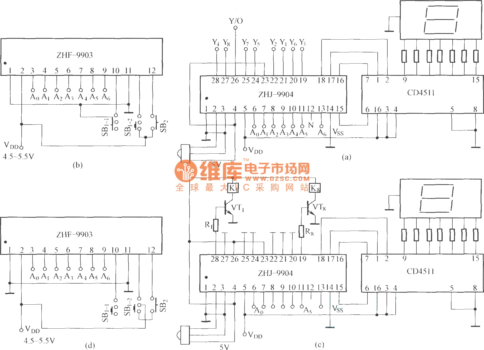
This is an eight-way signal remote control selection circuit composed of ZHJ-9904. It includes a remote control transmitter circuit, an eight-way switch control circuit, and a remote control transmitter. The eight-way signal remote control selection circuit utilizing the ZHJ-9904 is...