
Brake Light Signal Module

The circuit operates by utilizing an integrated circuit (IC) that features an internal oscillator capable of producing a square wave signal. The frequency of this signal is crucial as it determines the flashing rate of the LED array. By employing flip-flops, the output frequency at pin #4 is effectively reduced, allowing for a controlled flashing pattern of the LEDs. The adjustment of resistor R3 provides flexibility in setting the desired flashing frequency, accommodating various visibility requirements.
When the brakes are applied, a positive signal is fed to the cathode of diode D1, which triggers the circuit to count five pulses before stopping the oscillator. This mechanism ensures that the LED array only flashes for a predetermined duration, enhancing the effectiveness of the visual alert. The combination of capacitor C2 and resistor R1 plays a pivotal role in resetting the IC, allowing the system to react promptly to the application of the brakes.
Transistor Q1 is employed as a driver for the LED array, providing the necessary current to illuminate the LEDs. The design ensures that when pin #4 of IC1 transitions to a low state, Q1 is activated, allowing current to flow through the LED array and illuminating the lights. This configuration not only enhances the visibility of the vehicle but also ensures that the alerting signal is clear and effective for other road users. Overall, this circuit design prioritizes safety and visibility, making it an essential component for vehicles in situations where stopping or slowing down may pose a risk to both the driver and other road users.Circuits of this kind are intended to drive LED Arrays in order to create more visibility and conspicuity when a vehicle is stopped or stopping. This circuit, in particular, will emit a visual alerting signal of 4 short flashes, followed by a steady on light that remains steady on as long as the brakes are applied.
IC1 internal oscillator generate s a square wave whose frequency is divided 64 times by the flip-flops contained in the chip in order to obtain about 1 to 4Hz at pin #4: this is the LED Array flashing frequency and can be set to the desired value by means of R3. A positive signal at D1 Cathode stops the oscillator after 5 pulses are counted. C2 and R1 automatically reset the IC whenever the brakes are applied. Q1 is the LED Array driver: LEDs will be on when pin #4 of IC1 goes low. 🔗 External reference
Related Circuits
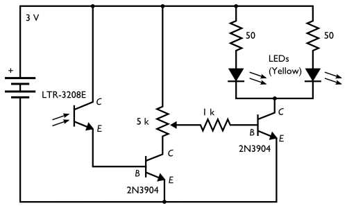
The concept involves placing a pair of yellow LEDs inside a pumpkin, combined with a photo sensor that activates the lights at night. The circuit is simple, utilizing minimal components. Two schematics are provided on the project site, with...

The multi-purpose signal generator circuit consists of integrated circuit oscillators and frequency dividers. It generates square waves ranging from high frequencies to sub-audio frequencies and also produces a frequency standard in the VHF range. The alternative oscillator section feeds...
The terminal of R7, indicated by an arrow, must be connected to the desired output pin of IC2 or IC3 to select the number of LEDs or clusters that will form the bar. For instance, to drive seven LEDs...
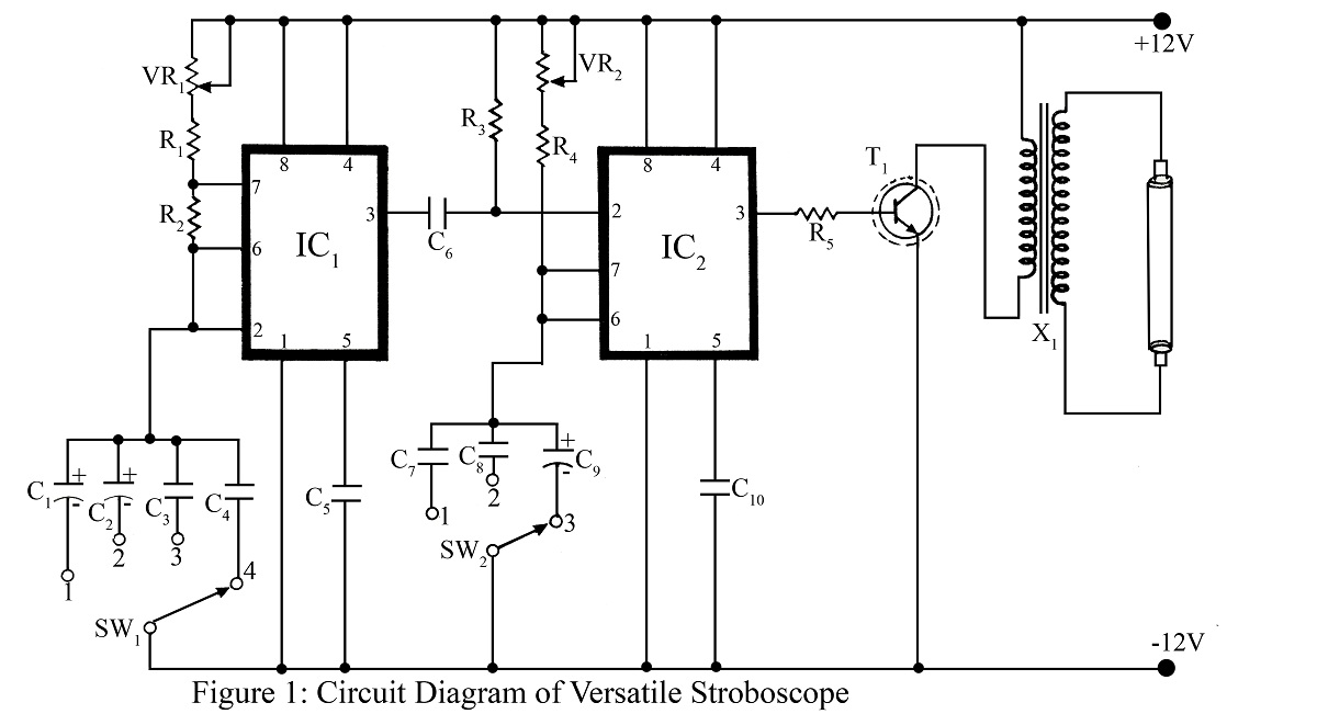
A stroboscope is an instrument used to observe rapidly moving objects with periodic motion as if they are stationary. The strobe light flashes at a frequency that synchronizes with the rotation of a wheel or moving object, creating the...
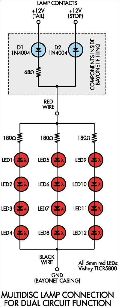
Before proceeding with the implementation, it is important to ensure that the output brightness is adequate for a stop and tail-light application. The light output may vary based on the tail-light lens and reflector assembly, so caution should be...
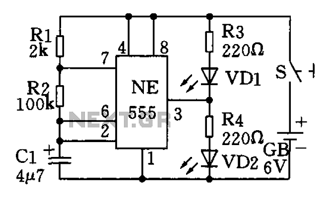
The circuit utilizes a 555 timer as the central component of a flashing light circuit. In normal operation, the light-emitting diodes (LEDs) VD1 and VD2 alternate flashing. The circuit comprises the NE555 timer, resistors R1 and R2, and capacitor...
Warning: include(partials/cookie-banner.php): Failed to open stream: Permission denied in /var/www/html/nextgr/view-circuit.php on line 713
Warning: include(): Failed opening 'partials/cookie-banner.php' for inclusion (include_path='.:/usr/share/php') in /var/www/html/nextgr/view-circuit.php on line 713