
LCD Module Control with PC
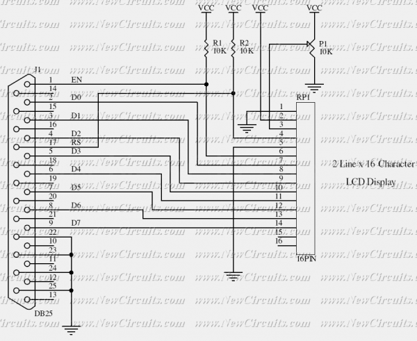
The circuit described is designed to interface a 2-line by 16-character Liquid Crystal Display (LCD) with a personal computer through a parallel printer port. The parallel port serves as a communication interface, allowing data and control signals to be sent from the PC to the LCD module. The circuit does not utilize the bi-directional capabilities of modern printer ports, making it compatible with a wide range of older parallel ports.
The LCD module operates using a set of control signals, specifically the Enable (E) and Register Select (RS) pins, which are essential for its operation. In this configuration, the Enable pin is responsible for signaling the LCD when to read the data present on the data pins, while the Register Select pin determines whether the data being sent is command data or character data. Both of these pins are connected to the Control Port of the parallel interface.
The Control Port is configured as an open collector or open drain output. This configuration allows multiple devices to be connected to the same line without risk of contention, as the output can only pull the line low, and an external pull-up resistor is required to pull the line high when not driven low. While many parallel ports include internal pull-up resistors, some do not, which necessitates the incorporation of external pull-up resistors in the circuit to ensure proper operation.
The data pins of the LCD are typically connected to the data lines of the parallel port, allowing for the transmission of character data. The circuit may also include additional components such as resistors and capacitors to stabilize the power supply and filter noise, ensuring reliable operation of the LCD module.
Overall, this circuit is a practical solution for displaying text from a PC on a standard LCD module, leveraging the simplicity and accessibility of the parallel printer port interface. The design is particularly useful for applications where a low-cost and straightforward display solution is required.This simple circuit controls a popular 2-line x 16-character LCD by a PC via printer port. It doesn't use the Bi-directional feature found on newer printer ports, thus it should work with most, if no all Parallel Ports. These LCD Modules are very common these days, and are quite simple to work with, as all the logic required to run them is on board.
The LCD panel's Enable and Register Select is connected to the Control Port. The Control Port is an open collector / open drain output. While most Parallel Ports have internal pull-up resistors, there are a few which don't. Therefore by incorporating the 🔗 External reference
Related Circuits
Liquid-crystal displays (LCDs) are available in various sizes and configurations, including their pinouts. Many of these displays require the manufacturer's documentation for proper usage, which is often difficult to locate when needed. Consequently, a small tester designed to identify...
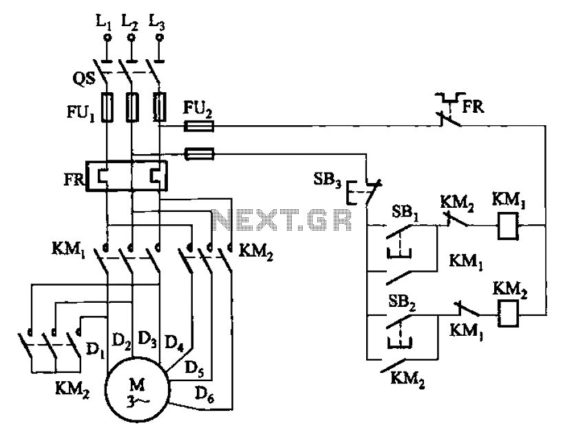
The circuit illustrated in Figure 3-97 features two contacts and is designed specifically for a 2kW dual-speed motor. In this configuration, SB1 is utilized for low-speed operation, while SB2 serves as the high-speed run button. The circuit operates by allowing...
There is no prior experience in building controllers, and there is uncertainty about how to begin. A budget constraint of less than 100 euros is present. A power thyristor is already available. The inquiry revolves around the best method...
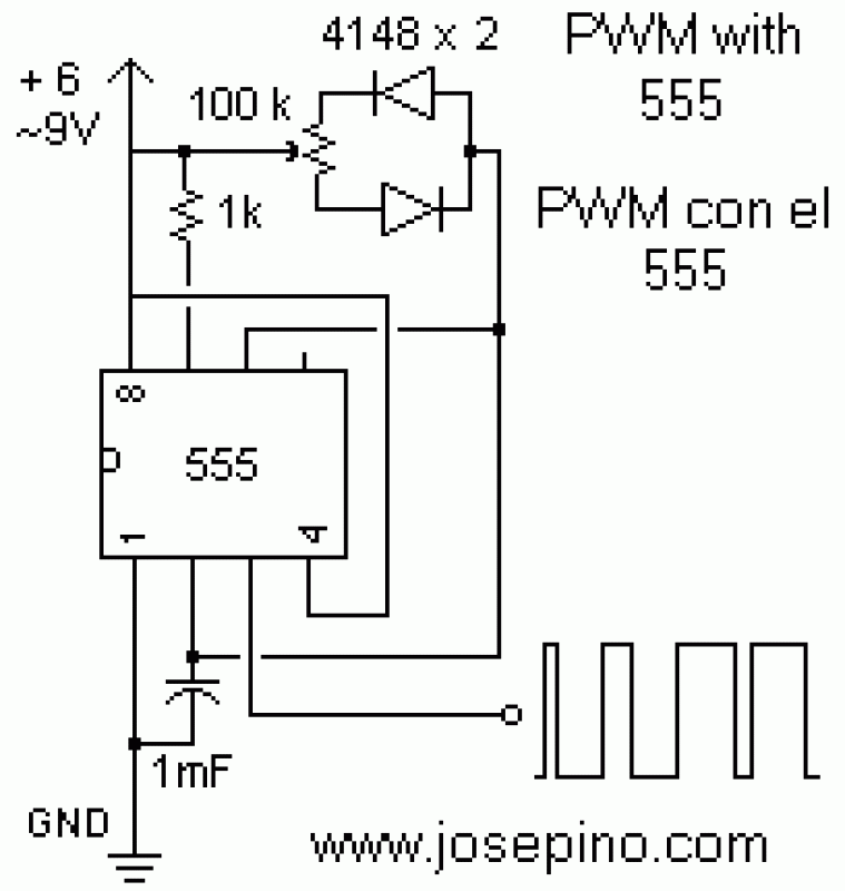
Pulse width modulation (PWM) is a technique to control analog circuits with a digital output. PWM is used in many applications, especially to control light intensity and speed on motors. A PWM circuit makes a square wave with a...
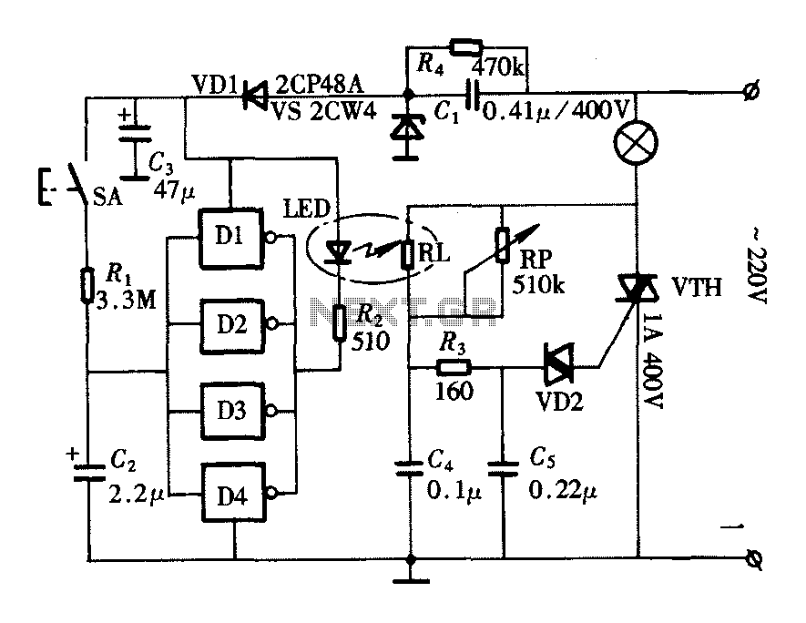
The lighting controller depicted in the figure features a gradual dimming function that prevents sudden brightness changes, which can irritate the human eye and potentially cause damage due to inrush currents. The circuit design includes a six-stage CD4069 inverter...
The second half controls the steering. The mechanical design is a 3 wheeled caddy with the single wheel actually a closely spaced pair of wheels which are driven by the main drive motor to provide motive power (this is...
Warning: include(partials/cookie-banner.php): Failed to open stream: Permission denied in /var/www/html/nextgr/view-circuit.php on line 713
Warning: include(): Failed opening 'partials/cookie-banner.php' for inclusion (include_path='.:/usr/share/php') in /var/www/html/nextgr/view-circuit.php on line 713