
Miller oscillator
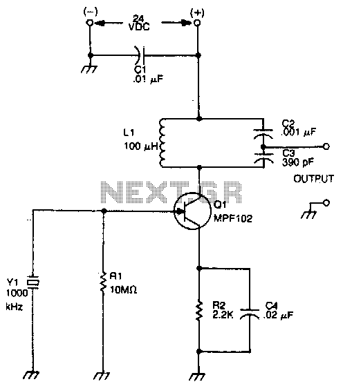
The JFET (Junction Field-Effect Transistor) Miller oscillator is a type of oscillator circuit that utilizes the properties of a JFET to generate oscillations. In this configuration, the drain terminal of the JFET is connected to an LC tank circuit, which consists of an inductor (L) and a capacitor (C). This tank circuit is crucial for determining the oscillation frequency.
The resonant frequency of the LC tank circuit is given by the formula:
\[ f_0 = \frac{1}{2\pi\sqrt{LC}} \]
where \( f_0 \) is the resonant frequency, \( L \) is the inductance, and \( C \) is the capacitance. The design of the tank circuit allows it to resonate at the same frequency as the crystal, ensuring that the oscillator operates efficiently.
The JFET in the Miller oscillator configuration also provides gain and feedback. The feedback loop is formed by connecting a portion of the output signal from the drain back to the gate of the JFET. This feedback is essential for sustaining oscillations. The gain provided by the JFET must be sufficient to overcome losses in the circuit to maintain continuous oscillation.
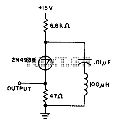
In summary, the JFET Miller oscillator's design, which incorporates an LC tank circuit tuned to the resonant frequency of a crystal, enables the generation of stable oscillations. This configuration is widely used in applications requiring precise frequency generation, such as in radio frequency (RF) circuits and signal processing systems. Proper selection of the inductor and capacitor values is essential to achieve the desired frequency characteristics while ensuring stability and reliability in the oscillator's performance.The drain of the JFET Miller oscillator is tuned to the resonant frequency of the crystal by an LC tank circuit. 🔗 External reference
Related Circuits
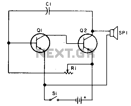
Oscillator, operates with 2 to 12 volts DC (optimal performance is achieved at 9 to 12 volts for maximum volume and clear keying). Additionally, R1 can be substituted with a 500K potentiometer, allowing the circuit to sweep across the...
The circuit operates within a frequency range of 15 Hz to 30 kHz and serves as a function generator. The 2N2926 transistor or its equivalent can be utilized in this design. This function generator circuit is designed to produce a...
The capacitor charges until the switching voltage is reached. When the switch (SUS) is activated, the inductor causes the current to oscillate. When the current through the switch drops below the holding current, the device turns off, and the...
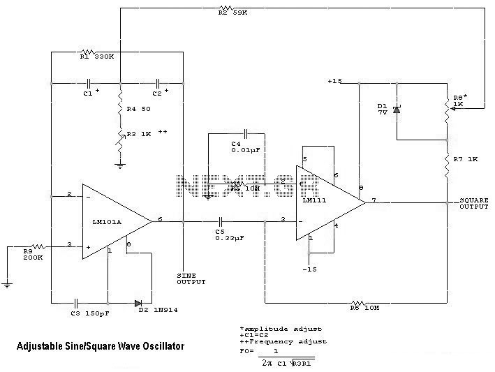
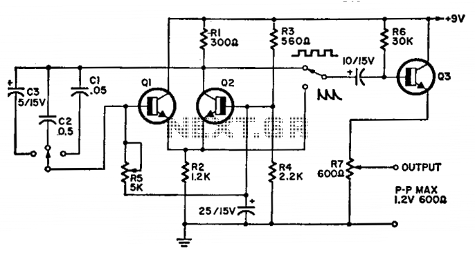
The following diagram illustrates the schematic of a simple, easily tuned adjustable sine and square wave oscillator. This circuit generates sine and square wave signals at frequencies ranging from below 20 Hz to above 20 kHz. The advantage of...
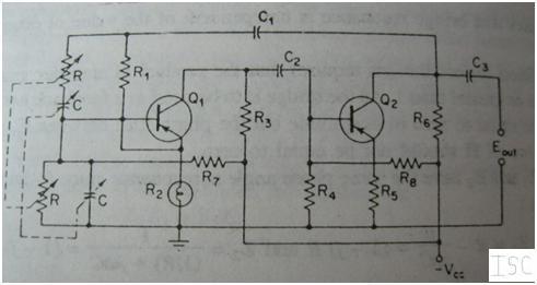
This article explains the construction and working of feedback oscillators, with a detailed description of the Wien bridge oscillator and phase shift oscillator, along with their circuit diagrams, basic components, and practical applications. Oscillators are electronic devices that produce...
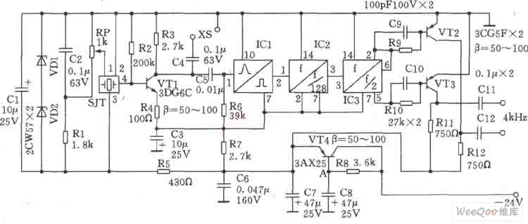
This circuit is a 1024 kHz temperature-compensated crystal oscillator. The circuit theory is illustrated. Due to the low output signal level of the circuit, a buffer using the following transistor VT1 is implemented for amplification. The base bias resistor...