
Mini Audio Amplifier Circuit Schematic Diagram BC547 Transistor

The Mini Audio Amplifier Circuit is designed to amplify low-level audio signals while maintaining low power consumption and compact size. The circuit typically incorporates a push-pull configuration using complementary transistors, which allows for efficient amplification of audio signals. This configuration helps to minimize distortion and improve linearity, ensuring high-quality audio output.
In this circuit, the input audio signal is fed into the base of the first transistor, which acts as a voltage amplifier. The output from this transistor is then fed into the second transistor, configured in a push-pull arrangement. This arrangement allows for both halves of the audio waveform to be amplified, providing a more complete and accurate representation of the original signal.
The power supply for this circuit is designed to operate at low voltage, typically around 5V, which contributes to the low power consumption of less than 3mA. This makes the circuit suitable for battery-powered applications where efficiency is critical. The output is typically connected to small speakers or headphones, making it ideal for portable audio devices.
Overall, the Mini Audio Amplifier Circuit is a practical solution for applications requiring audio amplification with minimal power usage and compact design, making it suitable for various consumer electronics.The following circuit shows about Mini Audio Amplifier Circuit Schematic Diagram. Features: power less than 3mA, small output, using push-pull .. 🔗 External reference
Related Circuits
The LM317 integrated circuit (IC) is commonly recognized as an adjustable voltage regulator. However, it also has the capability to function as an audio amplifier, specifically in Class A configurations. The LM317 can be utilized in audio amplification applications due...
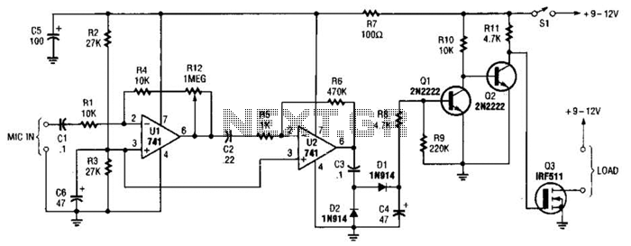
This audio-controlled switch integrates a pair of 741 operational amplifiers, two 2N2222 general-purpose transistors, an hcxFET, and several supporting components into a circuit capable of activating devices such as a tape recorder, a transmitter, or virtually any sound-activated equipment. The...
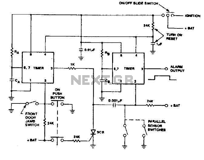
The 555 timer generates a reliable delay, enabling the driver to deactivate the alarm and eliminating the need for an external control switch that could be compromised. Additionally, the RCS prevents the activation of timer B unless it is...
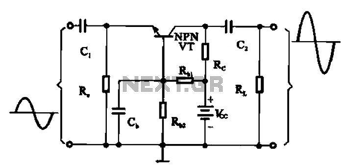
A common base transistor amplifier circuit is characterized by its basic structure, which includes key components such as a biasing resistor, capacitors for coupling, and an amplifying transistor. The circuit features four resistors that establish the quiescent point, with...
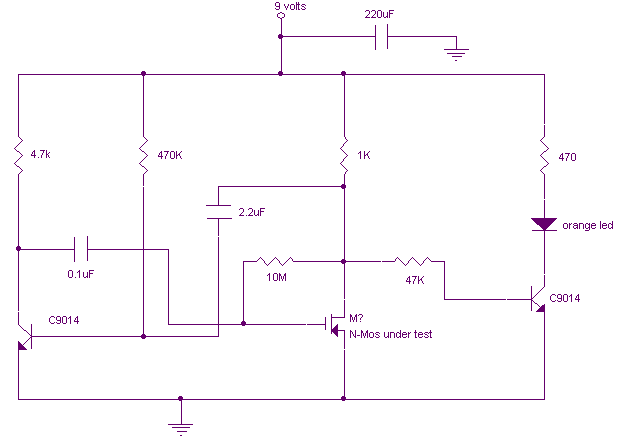
This is a variation on the astable multivibrator. Circuit was recently developed to test for N-mosfets (the power kind e.g. irf830). I don't claim circuit can test all bad mosfets or all fault mosfet conditions. If mosfet is working...
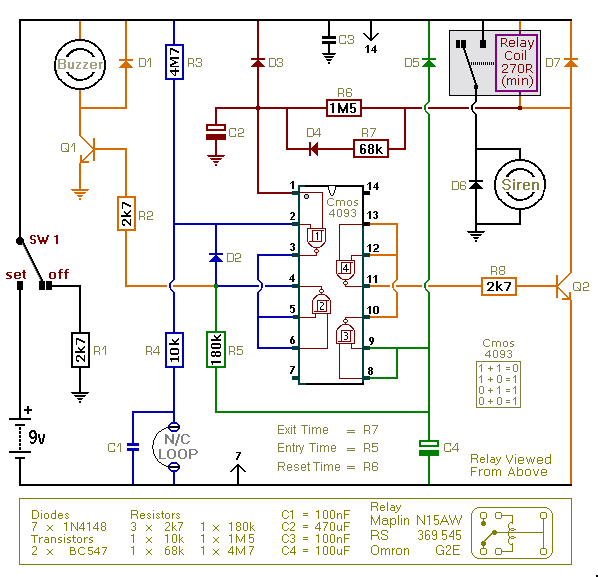
This is an improved version of the basic Garage/Shed Alarm. The Entry and Exit delays have been extended to approximately 30 seconds, and a timed Siren cut-off along with an automatic reset feature has been added. Additionally, the LED...