
Frequency Divider For Measurements Circuit

The circuit utilizes the 7490 decade counter, which is a versatile integrated circuit capable of counting from 0 to 9 and can be configured for various counting applications. In this configuration, the 1-MHz input signal is fed into the first 7490 counter (U1), which divides the frequency by 10, resulting in a 100 kHz output. This output can then be connected to the next counter stage (U2), further dividing the frequency by 10 to yield a 10 kHz signal.
Each subsequent 7490 counter (U3, U4, U5) continues this division process, allowing for precise control over the output frequency. The division ratio can be adjusted by tapping off at various stages, providing flexibility in application. For instance, if a 1 kHz output is desired, the output can be taken from U4, while a 100 Hz signal can be accessed from U5.
The design allows for the addition of extra counter stages if even lower frequencies are needed. This modularity is beneficial for applications requiring a broad range of output frequencies from a single high-frequency source. Proper power supply decoupling and grounding are essential to ensure stable operation and to minimize noise in the output signal. Additionally, appropriate resistor and capacitor values should be selected to optimize the performance based on the specific requirements of the application. This circuit is meant to be driven by a 1-MHz standard signal of a few volts amplitude. Ul through U5 are 7490 decade counter/divider and produce a division ratio of 100,000:1. Successive divisions of 10 can be tapped off, if desired, between stages. One or more stages can be added for still lower frequencies.
Related Circuits
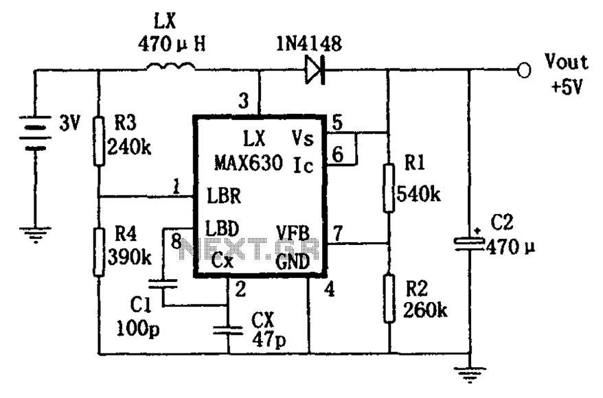
A low voltage frequency circuit utilizes the MAX630 for low battery voltage detection, functioning as an offset boost converter power supply. It is designed to maintain high efficiency (85%) while providing a DC output voltage of 5V at a...
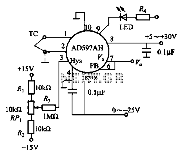
An automatic electric furnace temperature controller is illustrated. The closed circuit consists of a temperature detection output control loop; as the temperature increases, the output voltage rises until it reaches a preset temperature value, at which point the output...
This characterization circuit, along with a PC and specific software, accurately measures the complete discharge cycle of a rechargeable AA cell. The capacity and output resistance of the cell can be easily determined from the resulting curve of these...
Creating circuit boards can be a challenging task. It requires designing a schematic, testing it on a breadboard, laying out the board, and finally printing and etching the board. Fortunately, Fritzing offers a solution. Fritzing is a free, open-source...
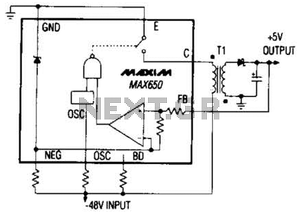
The Max650 switching regulator generates a regulated 5 V output from large negative voltages, such as the -48 V commonly found on telephone lines. This power supply requires several external components, including a transformer, and is capable of delivering...
The fundamental principle of the theremin is the heterodyne oscillator. In the development of the Open Theremin, a stable and reliable oscillator was essential. Various schematics featuring different components were researched and constructed on small boards, which were then...