
Mini Headphone Amplifier
The volume pot should be a linear type and would give, with the 15k resistor in parallel, the benefits outlined in ESP's A Better Volume Control.
The crossfeed is on a separate board in the prototype. I mounted it vertically on the main board using hot-melt glue. All the switches, jacks and volume control were also mounted on the enclosure using a hot-melt glue gun. I used generous amounts of hot-melt glue around the bases of all the capacitors as they are more susceptible to lead and track breaking due to vibrations. My prototype uses two 9V alkaline batteries to give 9-0-9V supply. I get around 20 hours of operation at normal portable listening levels. The effect of the demise of a few pairs of alkaline batteries on my wallet has decided me to switch over to rechargeable batteries. A battery charger is now under construction.
This amp can also be powered by Project 05 using a 15-0-15V transformer. A 5VA transformer should have oomph enough for the job. The first thing that you notice about the sound is the authority of the low frequency. The sensation of the kick drum's 'kick' (pun intended) on the earlobes greatly enhances the listening experience. Only now do I realise the full potential of the Sennheiser PMX 60.
With the crossfeed on, the vocal that used to seem to be right on top of one's nose is pulled forward. The perceived depth in the sound stage and the bass is very much dependent on the source material. For some materials, loss in bass is experienced with the crossfeed on. This is due to the cancellations of the unrealistic, out-of-phase signals. A star ground was not necessary for my battery powered version but is recommended for a mains powered one. Use the common point of the power filter caps as the ground return and employ a ground loop breaker if you use a metal enclosure. For the enclosure, I chose what used to be a part of a plastic school lunch box. I measured and marked the spots for the cuts I had to make. A sharp hobby-knife, a drill bit, a tabletop vise and a steady hand were all that I needed for the job. When working with plastic, it's a very good practice to measure twice and cut once (he spake from bitter experience).
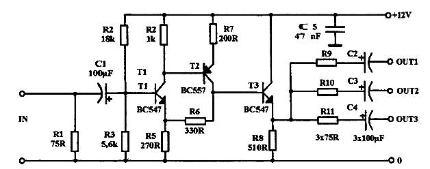
The circuit features a bypass switch (SW1) that allows the user to bypass the crossfeed network, which is essential for maintaining audio integrity. The inclusion of a 100k resistor that bridges the bypass switch minimizes unwanted noise artifacts such as crackles or clicks that may arise during operation. This resistor is a critical component of the crossfeed network, and its omission would lead to undesirable audio performance. Resistors R6 and R9, while specified at 4.53k, can be substituted with 4.7k resistors without compromising the circuit's functionality.
The NE5532 operational amplifier is employed as the primary amplification component in this design. This choice is based on the source being a PDA's internal DAC, which does not necessitate the use of high-end opamps. However, alternatives such as the LM6171, OPA2134, OPA2132, OPA134, and OPA4134 are available for those seeking to enhance audio quality. The use of IC sockets is recommended for flexibility in upgrading opamps in the future.
The volume control utilizes a linear potentiometer in conjunction with a 15k resistor, optimizing the audio output as per the guidelines provided in ESP's A Better Volume Control. The crossfeed network is located on a separate board, which is vertically mounted on the main board using hot-melt glue, ensuring stability and resistance to vibrations. Careful application of hot-melt glue around capacitor bases further enhances durability against mechanical stress.
Powering the prototype is achieved through two 9V alkaline batteries configured for a 9-0-9V supply, providing approximately 20 hours of operation at standard listening levels. A transition to rechargeable batteries is planned due to cost considerations associated with battery replacements. The circuit can alternatively be powered by a 15-0-15V transformer from Project 05, with a 5VA transformer deemed sufficient for operation.
The audio characteristics of the amplifier are highlighted by a pronounced low-frequency response, enhancing the listening experience, particularly with percussion instruments. The crossfeed feature modifies vocal positioning within the soundstage, adding depth, though it may result in bass loss depending on the audio source due to phase cancellations.
For grounding, while a star ground is not essential for battery-powered designs, it is advisable for mains-powered circuits. The common point of power filter capacitors serves as the ground return, with a ground loop breaker recommended for metal enclosures to prevent interference. The enclosure, repurposed from a plastic school lunch box, was crafted with precision tools, emphasizing the importance of careful measurement during assembly.SW1 bypasses the crossfeed network. I have reconfigured the original crossfeed schematic so that now the 100k resistor always bridges the bypass switch and thereby reduces any 'crackle' or 'click' or whatever you may call them. Don't omit these 100K resistors as they form a part of the crossfeed network and omitting them would bear undesirable results.
Note that R6 and R9 are indicated as 4.53k, however the use of 4.7k resistors will be perfectly adequate in practice. I chose the NE5532 for this project. Since the source is a PDA's internal DAC, I didn't see the need to use premium opamps. Of course, if it makes you feel better, you can always use higher quality (expensive) opamps. Just make sure the opamp is capable of driving low impedances. LM6171, OPA2134, OPA2132, OPA134 and OPA4134 (dual) are some possible substitutes. It's likely that there are others. IC sockets are therefore a good idea if you have plans to upgrade the opamps. The volume pot should be a linear type and would give, with the 15k resistor in parallel, the benefits outlined in ESP's A Better Volume Control. The crossfeed is on a separate board in the prototype. I mounted it vertically on the main board using hot-melt glue. All the switches, jacks and volume control were also mounted on the enclosure using a hot-melt glue gun.
I used generous amounts of hot-melt glue around the bases of all the capacitors as they are more susceptible to lead and track breaking due to vibrations. My prototype uses two 9V alkaline batteries to give 9-0-9V supply. I get around 20 hours of operation at normal portable listening levels. The effect of the demise of a few pairs of alkaline batteries on my wallet has decided me to switch over to rechargeable batteries.
A battery charger is now under construction. This amp can also be powered by Project 05 using a 15-0-15V transformer. A 5VA transformer should have oomph enough for the job. The first thing that you notice about the sound is the authority of the low frequency. The sensation of the kick drum's 'kick' (pun intended) on the earlobes greatly enhances the listening experience. Only now do I realise the full potential of the Sennheiser PMX 60. With the crossfeed on, the vocal that used to seem to be right on top of one's nose is pulled forward.
The perceived depth in the sound stage and the bass is very much dependent on the source material. For some materials, loss in bass is experienced with the crossfeed on. This is due to the cancellations of the unrealistic, out-of-phase signals. A star ground was not necessary for my battery powered version but is recommended for a mains powered one. Use the common point of the power filter caps as the ground return and employ a ground loop breaker if you use a metal enclosure.
For the enclosure, I chose what used to be a part of a plastic school lunch box. I measured and marked the spots for the cuts I had to make. A sharp hobby-knife, a drill bit, a tabletop vise and a steady hand were all that I needed for the job. When working with plastic, it's a very good practice to measure twice and cut once (he spake from bitter experience).
🔗 External reference
Related Circuits
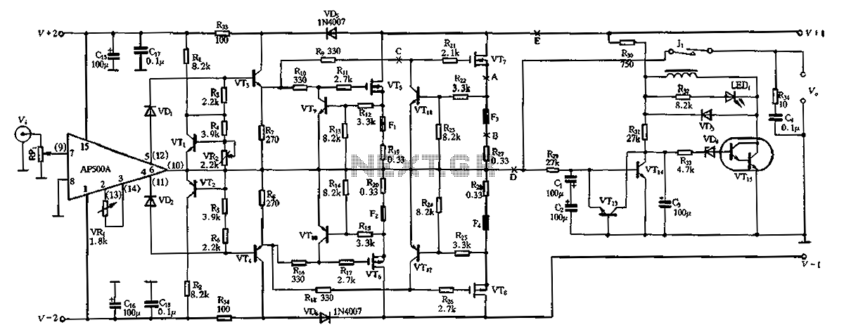
The CPI is a 100W DC super power amplifier circuit based on the AP500. It features a parallel push-pull amplifier output stage composed of transistors VT5, VT6, and VT7 to enhance output power. The circuit's output power is low...
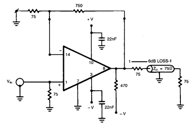
The NE5539 wideband operational amplifier can be readily utilized as a color video amplifier. The gain remains stable, varying less than 0.5% from the minimum to the maximum of the specified range. The maximum differential phase shift is around...
The three circuits described provide a constant current to the LED (or LEDs) when the supply voltage reaches 15V or higher. The second and third circuits can be activated or deactivated through the input line by turning on the...
Here is a little audio amplifier similar to what you might find in a small transistor radio. The input stage is biased so that the supply voltage is divided equally across the two complimentary output transistors which are slightly...
Video power amplifier circuit diagram. The circuit operates exclusively with AV compounds, where video and audio signals are transmitted separately. It is not suitable for connections involving "HF" antenna cables. Ensure that the video amplifier is included in the...
This is a mini strobe light. NE555 is used as a self-oscillator. The width of the output pulse is changed by the variable resistor. 25 msec means 40 Hz. 6 msec means 166 Hz. A LED is connected to...