
Mini Metronome

The described metronome scale involves a series of incremental tempo markings that are crucial for musicians to understand the pacing of their performance. This scale ranges from a slow tempo of 40 beats per minute (BPM) to a brisk tempo of 208 BPM, providing a comprehensive spectrum for practice and performance.
In an electronic metronome circuit, the implementation of such a scale involves several key components. The heart of the metronome is typically a microcontroller, which can be programmed to generate precise timing pulses at the specified BPM. The microcontroller interfaces with a timing circuit that may include a crystal oscillator to ensure accuracy.
The output from the microcontroller can drive a speaker or piezo buzzer, producing audible clicks or beeps at each metronome step. An LED may also be included to provide a visual cue that synchronizes with the audible output. The user interface may consist of buttons or a rotary encoder to allow the musician to select the desired BPM from the defined scale.
The circuit may also feature a display, such as a seven-segment or LCD screen, to show the current BPM selection. Power management components, including voltage regulators and capacitors, are essential to ensure stable operation of the circuit.
In summary, the electronic metronome circuit designed to accommodate the specified BPM scale would integrate a microcontroller, timing elements, audio output components, user interface controls, and power management features to deliver a reliable and user-friendly metronome for musicians.Finally mark the entire scale with the usual metronome steps as following: 40 - 42 - 44 - 46 - 48 - 50 - 52 - 54 - 58 - 60 - 63 - 66 - 69 - 72 - 76 - 80 - 84 - 88 - 92 - 96 - 100 - 104 - 108 - 112 - 116 - 120 - 126 - 132 - 138 - 144 - 152 - 160 - 168 - 176 - 184 - 192 - 200 - 208. 🔗 External reference
Related Circuits
The mine railway connects the national railways and intermediate links of the mining area, serving as an important component of the railway transport network. Statistics indicate that the Chinese mine railway extends over 20,000 kilometers, with numerous road junctions...
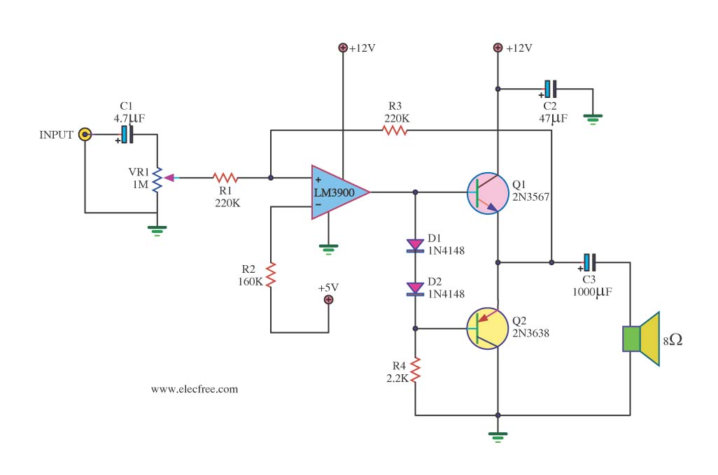
This mini audio amplifier will test the audio stages in amplifiers such as the front end of FM bugs. You can also use it on lots of our other projects as well as the output stages of radios. It...
The piezo diaphragm can originate from a music card, and if two or three diaphragms are available, they can be connected in parallel, as illustrated in the diagram, to observe their impact on the output frequency. The only component...
This is a mini-sized power amplifier rated at 2 watts OTL that utilizes the LM380 integrated circuit. It serves as a ready-made circuit for audio applications and communication, requiring minimal external equipment. The capacitor C6 can be selected from...
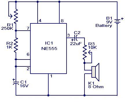
This weblog focuses on electronic circuit schematics, PCB design, DIY kits, and diagrams for electronic projects. A simple circuit utilizing the NE555 IC is presented, which can be employed to generate metronomes. This circuit is particularly beneficial for music...
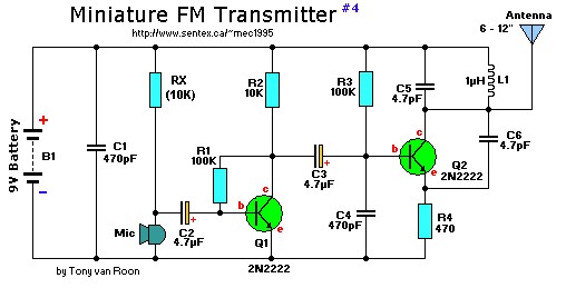
This is a mini FM transmitter designed by Tony van Roon, powered by two transistors. It is straightforward to assemble, and its transmissions can be received on any standard FM radio. The transmitter has an approximate range of 1/4...