
MINI PIEZO SIREN circuit

The described circuit is a classic example of a piezoelectric oscillator, utilizing a transistor to amplify the signal generated by the piezo diaphragm. The piezo diaphragm, acting as a capacitive element, converts mechanical vibrations into electrical signals. When multiple diaphragms are connected in parallel, their combined capacitance increases, which can significantly affect the resonant frequency of the circuit.
The transistor's role is crucial, as it serves as a switch and amplifier. When a small input current is applied to the base via the bias resistor, it allows a larger current to flow from the collector to the emitter. This action is amplified as the feedback winding induces additional current into the base, creating a regenerative feedback loop that sustains oscillation. The feedback mechanism is essential for maintaining continuous oscillation, as it ensures that the transistor remains in an active state.
The inductor, wound around a ferrite core, plays a significant role in the circuit's operation. The ferrite core enhances the magnetic coupling and allows for efficient energy transfer between the windings. The design of the feedback winding is critical; it must be optimized to ensure that the induced current is sufficient to keep the transistor in its active region without causing saturation.
The oscillation frequency of the circuit can be fine-tuned by adjusting the values of the piezo capacitance and the inductor's inductance. The parallel resonant circuit formed by the piezo and inductor allows for selective frequency response, making the circuit suitable for applications requiring specific frequency outputs, such as sound generation in musical devices.
Overall, this circuit exemplifies the principles of electronics involving transistors, inductors, and capacitors, illustrating the interplay between these components to achieve desired electrical characteristics and functionalities.The piezo diaphragm can come from a music card and if you have two or three diaphragms, they can be added in parallel-as shown on the diagram to see how they affect the frequency of the output. The only component you will have to make is the "transformer. " The circuit uses a transistor to drive a piezo and when we discuss the operation of a transistor we are describing TRANSISTOR ACTION. This is the action of a transistor amplifying the current entering the base and allowing a larger current to flow through the collector-emitter circuit. TRANSISTOR ACTION is simply another name for TRANSISTOR AMPLIFICATION. The circuit also demonstrates TRANSFORMER ACTION (the component across the piezo diaphragm is essentially an inductor with an over-wind to supply positive feedback to the base of the transistor).
These two windings demonstrate TRANSFORMER ACTION (the action of a waveform in one winding being passed to another winding. The waveform is passed via electro-magnetism - a magnetic field - and this is magnetism produced by electrical current.
) Transistor action is simply the amplifying action of the transistor. A transistor amplifies the current entering the base and causes a higher current to flow in the collector-emitter circuit. The ratio of these two is the gain of the transistor and is generally about 100, however the gain can range from 20 to 400 or more, depending on the type of transistor and the value of the surrounding circuit components.
The transistor amplifies the current about 100 times and allows the higher current to flow in the collector-emitter circuit. This is called TRANSISTOR ACTION or TRANSISTOR AMPLIFICATION. The base bias resistor is designed to partially turn the transistor ON and this causes a medium amount of current to flow through the collector-emitter circuit.
Connected to the collector is a coil of wire called an inductor. The wire is wound on a ferrite core. Ferrite is an iron material in which the particles of iron are surrounded by an insulating material so that the iron particles are magnetically separate. When current passes through the winding it produces EXPANDING MAGNETIC FLUX and this flux cuts the turns of the winding we have added, called the feedback winding.
This feedback winding is connected to the base of the transistor so that the current it produces is ADDED to the current supplied by the base-bias resistor and this causes a greater current to flow in the base of the transistor. The current continues to increase until the transistor is fully turned on and at this point in the cycle the flux is a maximum but it is NOT EXPANDING.
Only expanding flux cuts the turns of the feedback winding and produces a current in it. Stationary magnetic flux does not produce (induce) a current in the over-wind and thus the current produced by the feedback winding ceases. This causes less current to flow in the base of the transistor and the transistor turns off a slight amount (don`t forget, the base-bias resistor is still providing a small amount of turn-on current).
The current through the inductor reduces and the flux begins to reduce. This causes a collapsing magnetic field to be present and this flux cuts the feedback winding to produce a current in it of opposite polarity. The number of turns on the feedback winding is worked out by winding sufficient turns to get the circuit to work then removing a few at a time until the circuit fails to work.
A few turns are then added to guarantee operation. The energy from the feedback winding must be enough to maintain oscillation. As far as the circuit is concerned, a piezo is a capacitor of about 10n to 20n. The inductor and capacitor form a tuned circuit or PARALLEL RESONANT CIRCUIT and if the piezo is remo 🔗 External reference
Related Circuits
It had been a little over a decade since the invention of the transistor when this article appeared in the August 1959 edition of Popular Electronics. Transistors were still a mystery to many, including engineers, technicians, and hobbyists. Author...
This project involves a simple doorbell circuit featuring the UM66 melody integrated circuit (IC), which is well-known for its melody generation capabilities. The IC is housed in a TO-92 transistor package and consists of only three pins, functioning as...
The welder no-load power saver circuit consists of a current detection control circuit and a power saving control circuit, as illustrated in the accompanying chart. The current detection control circuit includes a current transformer (TA), a bridge rectifier (UR),...
A 6V to 12V DC converter circuit is designed to convert a lower voltage of approximately 6 volts to a higher voltage of 12 volts, albeit with a reduced current rating. This inverter circuit can deliver up to 800mA...
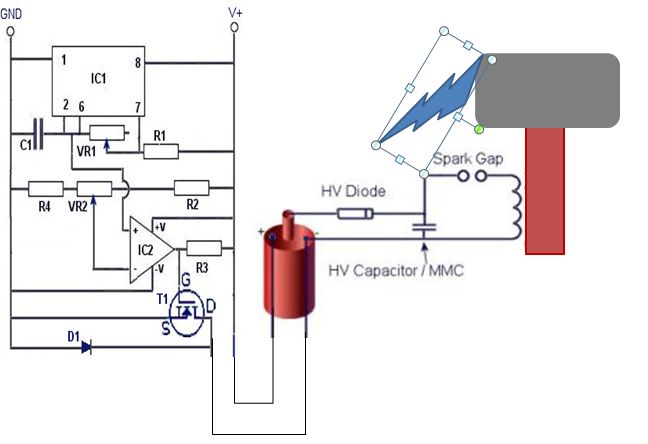
This coil operates from 12V or 24V SLA batteries. A pair of car ignition coils is used to provide approximately 20kV for charging the capacitor bank. The ignition coils are driven by a variable frequency square wave generated by...
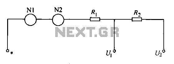
A voltmeter operates through a measuring mechanism in a specified circuit, utilizing a moving coil in series with additional resistance. The fixed coil is denoted as N1, while the moving coil is designated as N2. The additional resistances are...