Mini stroboscope
A strobe light generates a brief, intense pulse of electric current through a gas, resulting in a brilliant burst of light. The gas is typically one of two inert gases, xenon or krypton, which emit relatively white light when struck by fast-moving electrons from the electric current. Due to the complex electronic structures of krypton and xenon atoms, they emit light across a broad range of wavelengths, producing rich, white light during the current pulse. The substantial current required to sustain the brief arc in the strobe's gas is supplied by a capacitor. A high-voltage power supply charges the capacitor to a voltage ranging from 200 to 600 volts, often accompanied by a whistling sound. The capacitor plates are connected through the gas-filled flashlamp, which produces light once electric charges are injected into the gas. These initial charges are typically generated by a high-voltage pulse applied to a wire wrapped around the flashlamp's middle or to a metal reflector nearby. A cascade of collisions leads to a violent arc of charged particles flowing through the flashlamp, colliding with gas atoms and resulting in a brilliant flash of light that ceases when the capacitor's stored energy is depleted.
The design of this mini stroboscope utilizes components primarily sourced from an old pocket camera flash unit, along with some readily available inexpensive components. It is important to note that the high voltage present in camera flash units can pose a significant risk of electric shock. The energy storage capacitor can retain dangerous high voltage even after power is removed.
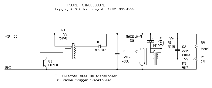
The operation principle involves Q1, R1, T1, and D1 forming a DC-DC converter that steps up the +3V voltage from batteries to between +200V and +500V, charging the main flash capacitor C1. Resistor R4 and potentiometer P1 create a voltage divider, with C2 charged from this voltage through R3. When C2 reaches 70V, the neon bulb N1 begins to conduct, triggering the triac Q2. The triac discharges C2 through the trigger transformer T2, generating a short high-voltage pulse (approximately 2.4 kV) that triggers the flash tube X1. Subsequently, the main flash capacitor C1 discharges through the flash tube, producing a bright flash, after which the charging of C1 recommences.
Components T1, T2, D1, X1, and N1 are salvaged from an old camera flash unit, while the remaining components are standard and widely available. Triac Q2 can be replaced with any suitable thyristor capable of withstanding 400V and a few amperes. Q1 can be substituted with any suitable power transistor rated above 2A and 40V, provided that R1 is adjusted to match the specifications of the chosen transistor. Experimentation with resistor values between 100 and 2000 ohms may be necessary to optimize circuit performance with the transformer T1 and transistor Q1 used.
The xenon flash tube X1 should operate within a voltage range of 200-400V and trigger at a voltage of 4 kV generated by T2. Caution is advised when constructing this circuit due to the presence of dangerous voltage levels. It is imperative to avoid contact with any components on the high-voltage side during operation. The circuit should be housed in an insulating enclosure, featuring a transparent plastic window in front of the flash tube. All components must be securely mounted to the circuit board, which should be firmly fixed within the enclosure. For use in environments such as parties, it is recommended to incorporate some level of resistance to liquids and mechanical stress.A strobe light passes a brief, intense pulse of electric current through a gas, which then emits a brilliant burst of light. The gas is usually one of two inert gases, xenon or krypton, that emit relatively white light when they`re struck by the fast moving electrons in the electric current.
Because krypton and xenon atoms have a great many electr ons and their electronic structures are very complicated, they emit light over a broad range of wavelengths. Thus the strobe emits a rich, white light during the moments while current is passing through the gas.
Supplying the enormous current needed to maintain the brief arc in the strobe`s gas is done with the help of a capacitor. A high voltage power supply pumps charge to the cpacitor (usually to 200-600V range). You can often hear a whistling sound as this power supply does its work. The capacitor plates are connected to one another through the gas-filled flashlamp that will eventually produce the light.
However, current can`t pass through the gas in the flashlamp until some electric charges are injected into the gas. These initial charges are usually produced by a high voltage pulse applied to a wire that wraps around the middle of the flashlamp or to the metal reflector near the flashlamp.
A cascade of collisions quickly leads to a violent arc of charged particles flowing through the flashlamp and colliding with the gas atoms. The flashlamp emits its brilliant burst of light that terminates only when the capacitor`s separated electric charges and stored energy are exhausted.
I build this mini strobosocope using compotents mostly taken from an old pocket camera flash unit and some cheap components I already had. On the picture below you can see the picture of the flash unit I used in my circuit (quite similar camera flash unit then can be bought from American Science & Surplus ): CAUTION - high voltage of camera flash unit can cause a nasty and possibly fatal shock.
The energy storage capacitor can retain dangerous high voltage after power is removed from the board. Principle of the operation: Q1, R1, T1 and D1 form a DC-DC converter to convert +3V voltage from batteries to +200.
+500V voltage which is charges the main flash capacitor C1. Resistor R4 and potentiometer P1 form a voltage divider and C2 is changed from that voltage though R3. When C2 reaches 70V voltage, the neon bulb N1 in the circuit starts to conduct and trigger the triac Q2.
Thyristor causes C2 discharge through trigger transformer T2, which generates a short high voltage (2. 4 kV) pulse which triggers the flash tube X1. Then main flash capacitor C1 discharges through flash tube and the tube generates a bright flash. The the charging of C1 starts again. Components T1, T2, D1, X1 and N1 were taken from old camera flash unit. There is nothing special in other components and they should be widely available. You can substitute Q2 with any suitable triac or thyristor which can withstand 400V and few amperes. You can also use any suitable power transistor (>2A and >40V voltage rating) as Q1 if you change the value of R1 to more suitable value fot that transistor.
Anyway you can try other values for (100 to 2000 ohms) to tune the circuit to work best with the transformer you are using as T1 and the transistor you are using as Q1. The xenon flash tube X1 should work at 200-400V voltage range and trigger at 4 kV triggering voltage generated by T2.
If you are constructing this circuit remember that the voltage in the curcuit are at dangerous levels. Do not touch any parts at the high voltage side of the circuit when it is operating. The circuit should be placed inside an insulating case like one above. There should be transparent plastic "window" in front of the flash tube. All parts should be well securated into the circuit board and the board should be well secured to the case.
If you are using this at parties, some level of resistance to liquids and mechan 🔗 External reference
