
stroboscope uses white leds

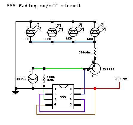
The stroboscope circuit is designed to provide visual indication of rotating objects through the use of high-intensity white LEDs. The circuit includes a microcontroller or timer IC to generate a pulse-width modulation (PWM) signal that controls the LEDs. The frequency of the PWM signal can be adjusted to match the rotational speed of the object being observed, allowing for effective stroboscopic effects.
The 16 white LEDs are arranged in a manner that maximizes light output and coverage. The LEDs are powered by a suitable power supply, ensuring that they operate at their optimal brightness. A heat sink may be incorporated to dissipate excess heat generated during operation, thus prolonging the lifespan of the LEDs.
The signal output to the frequency counter is typically derived from the same PWM signal driving the LEDs. This output can be connected to a microcontroller or dedicated frequency counter module, allowing for real-time measurement of the RPM of the rotating object. The circuit may include additional components such as resistors, capacitors, and transistors to ensure proper signal conditioning and LED driving capabilities.
Overall, this stroboscope circuit is suitable for various applications, including mechanical diagnostics, motion analysis, and educational demonstrations, where the visualization of fast-moving objects is required.This stroboscope circuit uses 16 high-brightness white LEDs in a torch housing and it provides a signal output to a frequency counter to provide a rev cou.. 🔗 External reference
Related Circuits
A circuit was constructed based on an LED beating heart frame instructable, but it is not functioning as expected. There is also mention of a built LED sequencer. The LED beating heart circuit typically involves a microcontroller, such as an...
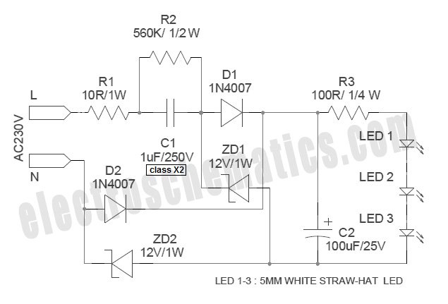
White Light Emitting Diodes (LEDs) now available can serve as a strong alternative to incandescent lamps in lighting applications. Today's White LEDs are... White Light Emitting Diodes (LEDs) represent a significant advancement in lighting technology, offering energy efficiency, longevity, and...

An LED, or Light Emitting Diode, is a semiconductor device that allows current to flow in one direction while blocking it in the opposite direction. This characteristic makes LEDs polarized components, having a positive side known as the anode...

The circuit in Figure 2 shows a 16-channel, AMI-encoded RF transmitter for data rates as high as 28.8 kbps. The circuit operates in the unlicensed (FCC Part 15) 902- to 928-MHz industrial, scientific, and medical (ISM) band and is...

This design concept addresses a major challenge associated with the use of photodiodes in high-speed applications such as barcode scanners, CD-ROMs, and DVDs, specifically the high output capacitance of the diode. The critical component in the circuit is the...
Every DIY enthusiast creates their own electronic dice using LEDs as indicators. This eliminates the need to physically throw the dice; instead, a button press activates the roll. The circuit design ensures fairness by preventing manipulation of the outcome,...