
AM Transmitter circuits
The AM transmitter circuit operates through the interaction of its primary components: the audio amplifier, RF oscillator, tank circuit, and the regenerative feedback mechanism. The audio amplifier processes the audio input signal, which is typically derived from a microphone or an audio source, and amplifies it to a suitable level for modulation.
The RF oscillator, centered around transistor Q1, generates a carrier wave at the desired frequency. The tank circuit, composed of inductor L1 and variable capacitor VC1, is critical for establishing the oscillation frequency. The inductance of L1 and the capacitance of VC1 form a resonant circuit that determines the frequency of oscillation. By adjusting VC1, the frequency can be finely tuned across the range of 500 kHz to 1600 kHz, allowing for flexible operation within the AM band.
For proper oscillation, Q1 requires regenerative feedback. This feedback is facilitated by connecting the base and collector of Q1 to opposite ends of the tank circuit. This configuration allows a portion of the output signal to be fed back into the input, reinforcing the oscillation process. The strength of the feedback can be adjusted to ensure stable oscillation without unwanted distortion or instability.
In summary, the AM transmitter circuit is a compact and efficient design that utilizes readily available components to achieve reliable transmission of amplitude-modulated signals within the medium wave frequency range. Proper tuning of the tank circuit and careful management of the feedback mechanism are essential for optimal performance.The AM Transmitter circuits in two and a half, audio amplifier and an RF oscillator. The oscillator is built around Q1 and associated components. Tank circuit L1 and VC1 is melodious from about 500kHz to 1600KHz. These components can be used from an old MW radio, if available. Needs Q1 regenerative feedback to oscillate and this is achieved by connecting the base and collector of Q1 to the opposite end of the tank circuit 🔗 External reference
Related Circuits
This circuit is a basic design that includes indicator LEDs and appropriate resistor values. A dotted line indicates that the IR LED is connected to the circuit via a length of wire (in this case, a telephone cable). The...
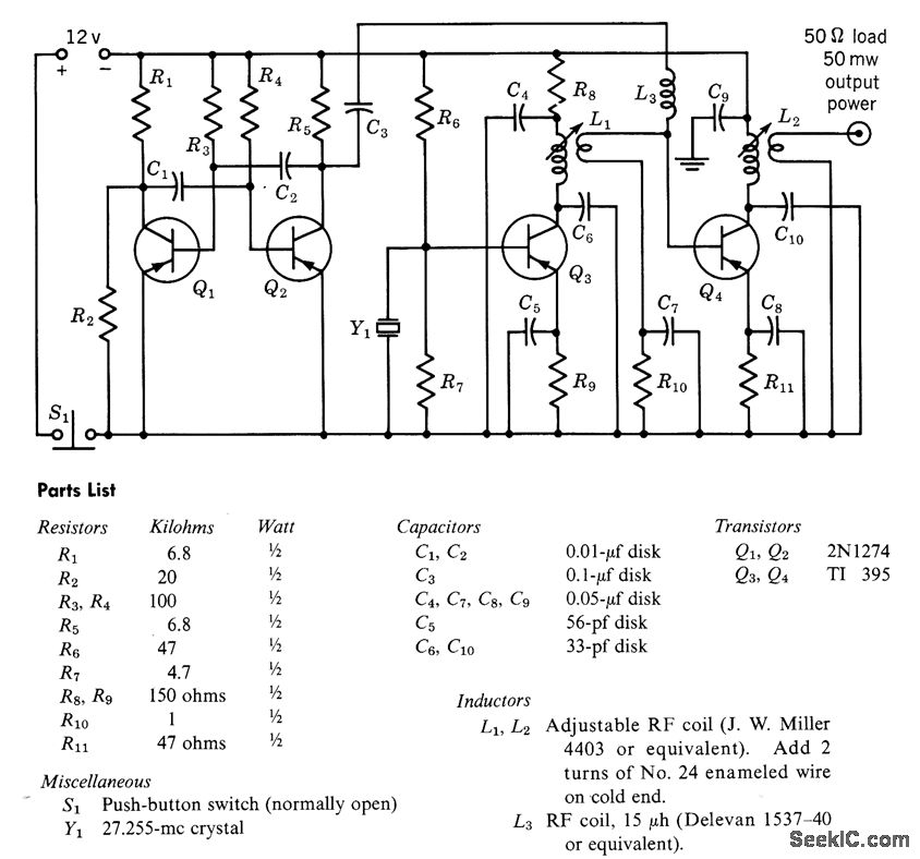
A free-running multivibrator activates power amplifier Q4 for audio applications. The operational range is approximately 1 mile, and capacitor C6 is used to tune the collector of the oscillator to the crystal frequency. - Texas Instruments Inc., "Transistor Circuit...
In this circuit, a 74HC14 hex Schmitt trigger inverter functions as a square wave oscillator to drive a small signal transistor configured as a class C amplifier. The oscillator frequency can be set to a fixed value using a...
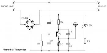
This circuit connects in series with a home phone line and transmits phone conversations through the FM band whenever the telephone handset is picked up. The transmitted signal can be tuned by any FM receiver. The circuit includes an...
This circuit is designed to support nine independent telephones using a single telephone line pair, allowing for operation at nine different locations. It includes a bidirectional telephone line simulator that does not require actual telephone lines, enabling the coupling,...
The game was originally designed to position three balls locked in holes on a slowly rotating ring around the Deadworld. Once the third ball was secured, a mechanical arm would release them, dropping the balls onto the playfield. This...
Warning: include(partials/cookie-banner.php): Failed to open stream: Permission denied in /var/www/html/nextgr/view-circuit.php on line 713
Warning: include(): Failed opening 'partials/cookie-banner.php' for inclusion (include_path='.:/usr/share/php') in /var/www/html/nextgr/view-circuit.php on line 713