
Misc. Circuits
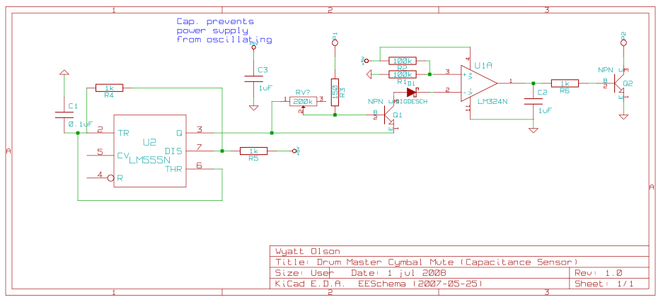
The described touch sensor circuit is designed to detect physical touch through a capacitive sensing mechanism. It operates by measuring changes in capacitance caused by the proximity of a conductive object, such as a finger, to the metal touch plate. The circuit consists of a capacitive touch plate connected to pin P1, which serves as the input for the sensor. The digital output is available on pin P2, providing a high or low signal based on the detected touch.
To optimize the sensitivity of the touch sensor, a variable resistor is included in the circuit. This resistor allows for fine-tuning of the sensor's responsiveness to touch, accommodating different environmental conditions and the physical characteristics of the touch plate. While a standard value of 200k ohms has been noted as effective, it is essential to experiment with different resistor values to achieve the desired sensitivity for specific applications.
In practical applications, this touch sensor can be integrated into various electronic projects beyond its initial design for a cymbal mute sensor. It can be utilized in interactive installations, touch-sensitive lighting controls, or as a simple switch in hobbyist electronics. The provided KiCad files facilitate easy modifications and adaptations for specific project needs, enabling users to customize the circuit layout and component values as required.
Overall, this touch sensor circuit exemplifies versatility in electronic design, providing a foundation for various creative applications while allowing for user-specific adjustments to enhance performance.Included on this page are various small circuits I have created over time. Some are trivial, some are a bit more complex, but hopefully all are useful in a variety of projects. Most include both the schematics as well as the source ( KiCad ) files. This is a touch sensor with adjustable sensitivity, which will output a digital signal specfying whe ther or not it is being touched. I originally created it as a cymbal mute sensor for my electronic drum hardware, although it could be used for any sort of touch sensitive switch. You would connect the metal touch plate to P1; the digital output is on P2. The exact value of the variable resistor will differ based on conditions, size of capacitance touch plate, etc; 200k seems to work for me, but you may need to adjust this a bit.
🔗 External reference
Related Circuits
This circuit utilizes a single 555 Timer IC along with a small transformer to generate high voltage for testing zener diodes with voltage ratings up to 50VDC. The 555 timer operates in astable mode, with the output from pin...

The circuit demonstrates a method for powering CMOS integrated circuits (ICs) using RS-232C lines. The MAX680 is typically employed to generate a voltage equal to ±2 Vcc. This circuit operates in the opposite manner, accepting ±10.5 to ±12V from...
This is a very simple project using a printed circuit board and 8 components. It will flash an ordinary 3mm or 5mm (1/8" or 1/4") LED at a rate of about one flash per second. This circuit works on...
In audio systems, noise signals are generally undesirable, and efforts are often made to eliminate them. Transistors can be utilized effectively for this purpose due to their availability and low noise characteristics. The following circuit serves as a Noise...
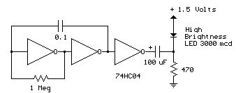
Several 1.5 V LED flasher circuits can be found online, and four of them are presented here. The flasher circuits operate on a single 1.5 V power supply. The design of a 1.5 V LED flasher circuit typically involves a...
Remove the 6 mm screw that secures the lower rear fairing cover. This cover is the black plastic piece to which the spark plug protectors are attached. Only the machine screw should be removed; do not detach the lower...
Warning: include(partials/cookie-banner.php): Failed to open stream: Permission denied in /var/www/html/nextgr/view-circuit.php on line 713
Warning: include(): Failed opening 'partials/cookie-banner.php' for inclusion (include_path='.:/usr/share/php') in /var/www/html/nextgr/view-circuit.php on line 713