
Fully Adjustable Power Supply
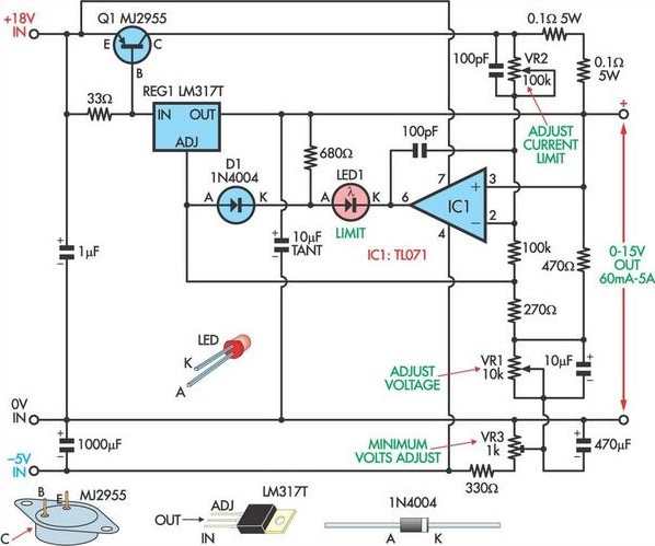
This circuit design effectively combines the functionality of an adjustable voltage regulator with current limiting capabilities, making it suitable for applications requiring precise voltage control and protection against overcurrent conditions. The LM317 serves as the primary voltage regulation component, while the MJ2955 transistor provides the necessary current amplification to exceed typical output limits. The use of a potentiometer for voltage adjustment allows for user-friendly customization of the output voltage, while the current sensing resistors ensure that the circuit can respond dynamically to load changes.
The inclusion of an op-amp comparator for current limiting enhances the reliability of the circuit, protecting both the regulator and the load from excessive current conditions. The design choice of employing a -5V reference voltage allows for a wider range of output voltage adjustment, which is particularly beneficial in applications where lower voltage levels are required. The LED indicator serves as a visual cue for the user, signaling when the circuit is operating in a current limiting mode.
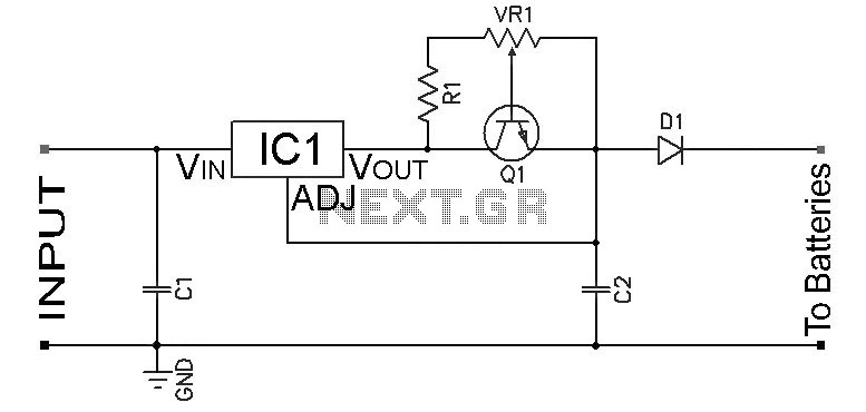
Proper thermal management is critical in this design, necessitating the mounting of the LM317 and MJ2955 on a shared heatsink. This ensures that both components can effectively dissipate heat, maintaining operational stability and preventing thermal shutdown. Overall, this circuit provides a robust solution for adjustable power supply applications, balancing performance with safety features.Based on a National Semiconductor application note, this circuit uses an LM317 3-terminal regulator (REG1), chosen because of its built-in over-current and over-temperature protection. Its output is boosted up to just over 5A by the MJ2955 transistor (Q1). The output voltage is varied by adjusting the voltage on REG1`s ADJ terminal using VR1 (a 10 kO potentiometer), via the 270O resistor. Adjustable current limiting is provided by op amp IC1, used as a comparator, which monitors the voltage across the 0. 1O current sensing resistors. Once this voltage exceeds a level set by potentiometer VR2, then its output goes low, dragging down the adjust pin of REG1 and thus the output voltage.
LED1 illuminates when current limiting is occurring. The 10kO voltage adjust potentiometer (VR1) has one side connected to -5V instead of 0V so that the output voltage can be varied down to 0V instead of 1. 2V (normal limit of an LM317). Trimpot VR3 is adjusted to set the minimum output voltage to +100mV or so. Note that because the -5V rail is used as a reference, it should be regulated using an LM7905 or similar.
The LM317 3-terminal regulator and Q1 should be mounted on the same heatsink to take advantage of REG1`s thermal control. 🔗 External reference
Related Circuits
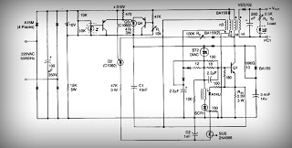
This is a low voltage, high-current output switching DC power supply with an input of 220 volts AC. In this circuit, an ST2 DIAC relaxation oscillator, Q3, C1, and the DIAC initiate conduction of the output switching transistor Q1....
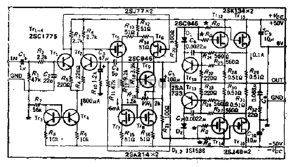
The circuit consists of three identical basic stages, with the second stage featuring a differential output from the power MOSFET, 2SJ77. A current mirror circuit utilizing 2SK214 is implemented. The operating current is 6mA; however, due to the power...
How many times have you wished that there was a simple way to turn on that sub-woofer or some other piece of audio equipment, simply by sending it a signal? This ability is fairly common in commercial subs and...
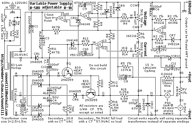
A reverse-engineered circuit diagram of a high-end commercial variable laboratory power supply. This unit is constructed using a standard operational amplifier and readily available components. While the design employs a single transformer with dual output windings, it can also...
Adjustable Constant Current Ni-Cd and Ni-MH Battery Charger Circuit. This circuit is designed to provide a constant current for charging Ni-MH or Ni-Cd batteries. A schematic diagram of the circuit is available. The adjustable constant current battery charger circuit for...
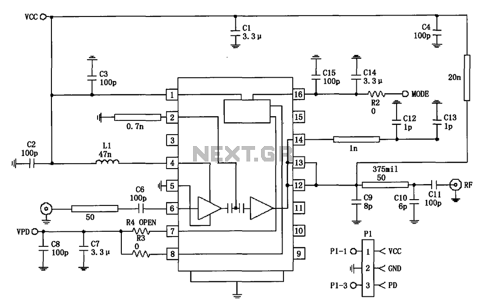
877 ~ 924MHz RF2152 power amplifier circuit diagram. The RF2152 is a high-performance power amplifier designed for applications in the 877 to 924 MHz frequency range. This amplifier is typically used in various RF communication systems, including wireless networks and...