
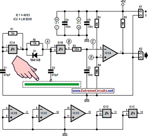
Sensor switch circuit 9 channels

The sensor switch circuit is designed to manage multiple sensor inputs efficiently, utilizing the 74HC147 priority encoder as its core component. The high input impedance of the 74HC147 allows for minimal loading on the sensors, which is crucial when using high-value resistors like 4.7 MΩ. This configuration ensures that the sensors can operate effectively without significant signal degradation.
In this circuit, each of the nine channels is connected to a separate sensor. When a sensor is activated, it pulls the corresponding input pin of the 74HC147 low, resulting in a logical output that indicates which sensor has been triggered. The output from the 74HC147 can then be fed into additional logic circuits or microcontrollers for further processing, enabling applications such as touch-sensitive interfaces or multi-sensor monitoring systems.
Resistors in the circuit serve dual purposes: they help establish the required input conditions for the 74HC147 and provide necessary pull-up functionality to maintain a stable logic high when the sensors are not activated. The circuit design emphasizes simplicity and reliability, making it suitable for various applications where multiple sensor inputs are needed.
Overall, the described sensor switch circuit is an effective solution for detecting multiple touch inputs with minimal component count while maintaining high performance and reliability.This sensor switch circuit has nine channels and consist of only three integrated circuits and some resistors. Due to high input impedance, 74HC147 allows to use of 4. 7 M resistors to create a logic level "high" to sensor inputs. When one sensor is touched, the resulting low resistance to ground circuit causes IC1 to read a logical level L.
🔗 External reference
Related Circuits
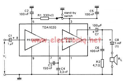
The TDA1020 is a monolithic integrated 12 W audio amplifier housed in a 9-lead single in-line (SIL) plastic package. Although it is designed primarily for car audio applications, it can also be utilized in various other audio applications. The TDA1020...
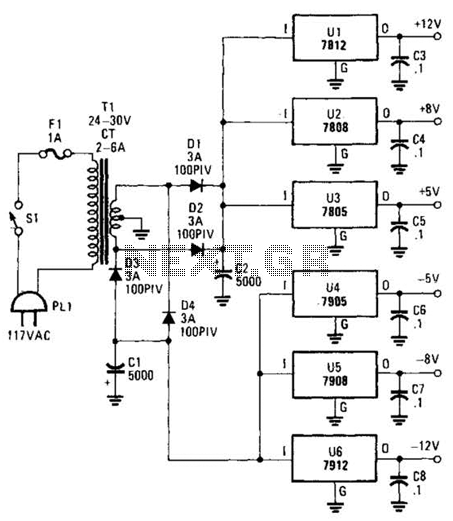
This dual-polarity, multivoltage power supply can be constructed with a minimal investment. The circuit utilizes 78XX and 79XX series voltage regulators, four 3-A diodes, a 24-30 V, 2-6 A transformer, and eight filter capacitors. The described dual-polarity, multivoltage power supply...
When VOUT is very low during startup or in the event of a short-circuit fault at the output, the switching regulator must operate at low duty cycles to keep the power switch current within the current limit range. This...
Capacitive touch sensors operate based on the electrical capacitance of the human body. When a finger approaches the sensor, it establishes a capacitance to Earth ranging from 30 to 100 pF. This phenomenon can be utilized for proximity detection...
AVC - The circuit regulates the volume line automatically, providing an output voltage of approximately 4 volts peak to peak. This voltage remains consistent. The Automatic Volume Control (AVC) circuit is designed to manage audio levels dynamically, ensuring a stable...
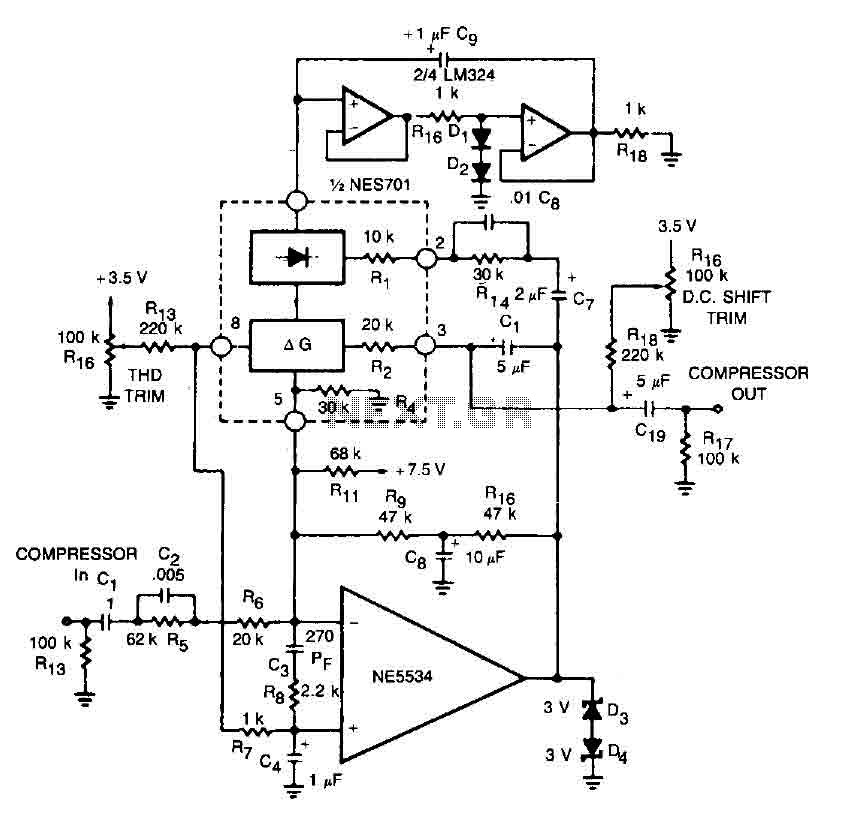
This circuit for a compressor utilizes a high-fidelity external operational amplifier (op amp) with high gain and wide bandwidth. A compensation network at the input is required for stability. The rectifier capacitor (Cg) is not grounded; instead, it is...