
Mobile cellphone charger with battery
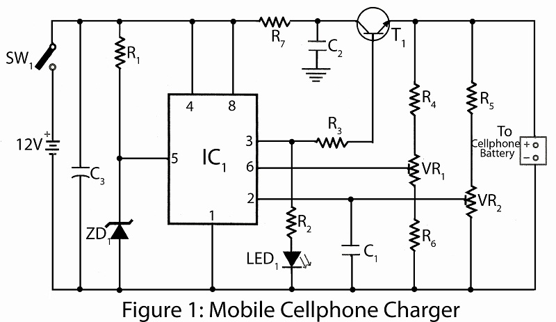
The circuit operates by leveraging the NE555 timer in astable mode, where it generates a pulse-width modulation (PWM) signal to control the charging process. The zener diode ZD1 stabilizes the voltage at pin 5, ensuring that the timer operates within the desired voltage range. The variable resistors VR1 and VR2 allow for fine-tuning of the charging voltage and threshold levels, enabling compatibility with various battery types and conditions.
When the battery is connected, the voltage at the trigger pin 2 is monitored. If this voltage drops below one-third of the supply voltage (VCC), the timer activates, causing output pin 3 to provide a high signal. This high signal energizes the transistor T1, which acts as a switch to allow higher current to flow into the battery, effectively charging it. The charging current can be adjusted by changing the resistance values of VR1 and VR2, which in turn affects the timing intervals of the NE555 and the voltage levels at the threshold and trigger pins.
As the battery charges and its voltage rises, the voltage at trigger pin 2 will eventually exceed one-third of VCC, causing the output at pin 3 to drop low, thereby stopping the charging process. This automatic cut-off feature helps prevent overcharging, which can damage the battery.
In summary, this circuit provides a simple yet effective solution for charging mobile batteries using AA cells, with adjustable parameters to accommodate different battery specifications. The use of the NE555 timer IC allows for precise control of the charging process, while the inclusion of a transistor enhances the current delivery capability.Here is a simple project using very common electronics components for charging mobile battery using AA cells. The main part of the circuit mobile cellphone charger is timer IC NE555, used to charge and monitor the voltage level.
IC1 get control voltage to pin 5 by zener diode ZD1 . Threshold pin 6 and trigger pin 2 is supplied with a voltage set by VR1 and VR2 respectively. The trigger pin 2 of IC1 is below 1/3VCC when discharge battery is connected to the circuit as a result flip-flop of IC1 is switched on to take output pin 3 high. The process is reversed when battery is fully charged of charged battery is connected. Here transistor T1 used to enhance the charging current from output pin 3 of IC1. Adjust potentiometer VR1 and VR2 as per require. 🔗 External reference
Related Circuits
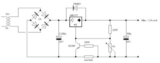
The battery charger circuit described is straightforward to assemble, requiring only a few inexpensive components and an additional winding on the power transformer (or a separate transformer). Since this charger operates independently of sound reproduction, there are no stringent...
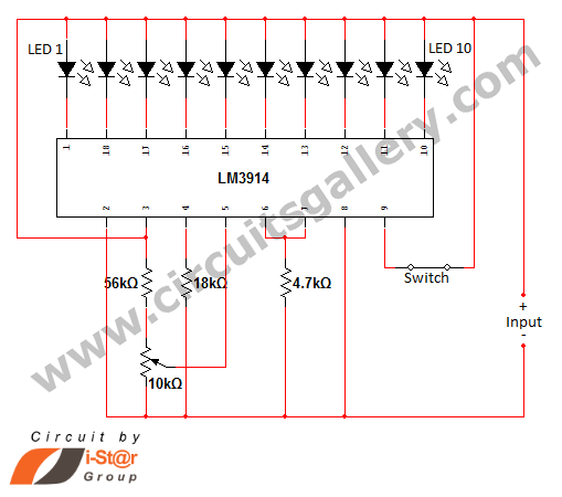
In various situations, it is necessary to indicate the amount of battery charge using methods such as LED dot displays or LED bar displays. This circuit utilizes the LM3914 integrated circuit to serve as a battery charge indicator with...
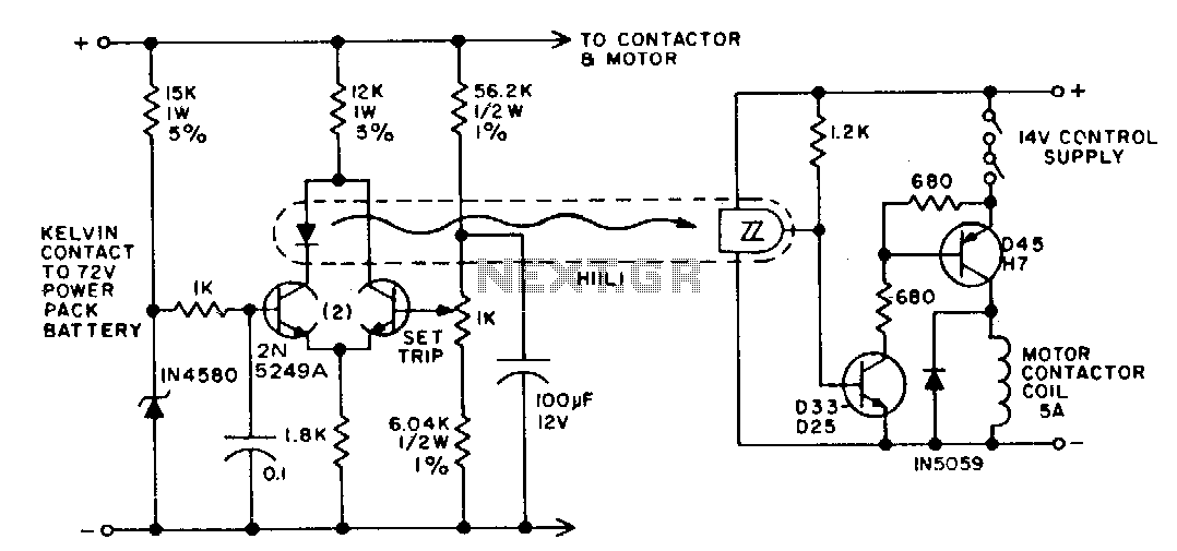
The battery life and operating cost of an electric vehicle are significantly impacted by the overdischarge of the battery. This circuit is designed to provide both a warning and a shutdown mechanism. An electronic switch is connected in series...
Often, outdoor audio or video recordings suffer from poor quality when the battery is low. If the battery voltage drops below 9V for a 12V recorder, the playback output will be compromised due to variations in the power supply. To...
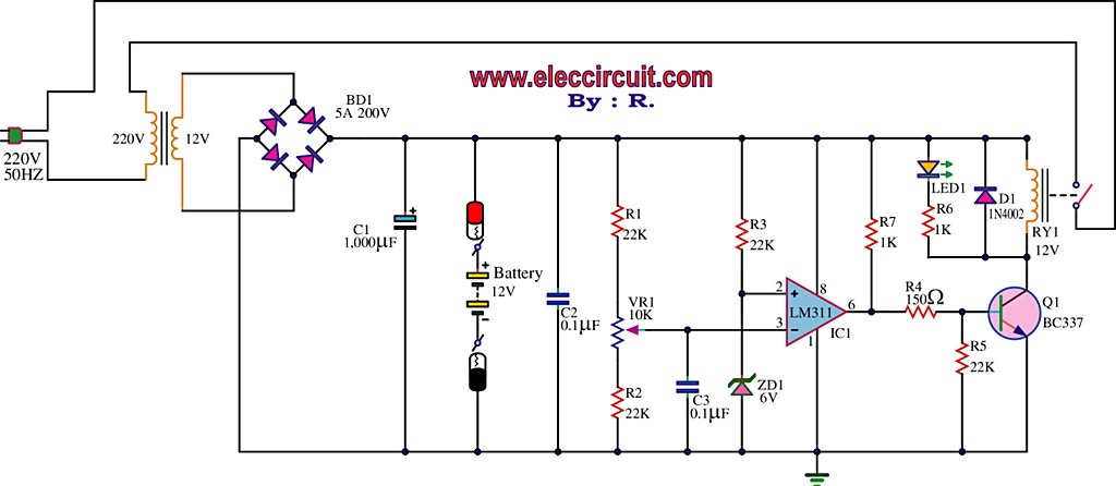
The best 12 Volt battery charger circuit is an automatic system that activates when the battery voltage falls below a specified threshold. This 12 Volt battery charger circuit is designed to efficiently charge lead-acid batteries while ensuring safety and longevity....
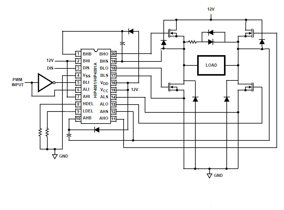
An individual is experiencing an unusual issue while utilizing an Intersil HIP4081A H-bridge driver integrated circuit (IC). The IC is connected to an Arduino microcontroller unit (MCU). The Intersil HIP4081A is a high-performance H-bridge driver designed for driving DC motors...