
Simple Battery State Indicator

To address the issue of battery voltage affecting the quality of audio and video recordings, a voltage monitoring and regulation circuit can be implemented. This circuit would continuously monitor the battery voltage and provide a stable output voltage to the recording device, ensuring that it operates within the optimal voltage range.
The schematic would typically include a voltage divider to step down the battery voltage for monitoring, an operational amplifier configured as a comparator, and a microcontroller or a simple transistor switch. The voltage divider consists of two resistors connected in series across the battery terminals, with the output taken from the junction of the resistors. This output is fed into the non-inverting input of the operational amplifier.
The inverting input of the operational amplifier is connected to a reference voltage, which is set to correspond to the minimum acceptable voltage for the recorder (in this case, 9V). When the battery voltage falls below this threshold, the operational amplifier's output will change state, triggering a response from the microcontroller or transistor switch.
The microcontroller can be programmed to activate an alarm or indicator light when the battery voltage is low, alerting the user to replace or recharge the battery. In addition, the circuit can include a buck converter to step down the voltage from the battery to a stable 12V output for the recorder, ensuring consistent performance even as the battery discharges.
Overall, implementing such a circuit will enhance the reliability of outdoor audio and video recordings by maintaining the necessary power levels for optimal operation.Many a time the outdoor audio or video recording becomes imperfect due to a ˜dying battery. If the battery voltage is less than 9V for a 12V recorder, the output during playback will not be of a good quality due to variations in the mo.. 🔗 External reference
Related Circuits
Phonographs are becoming increasingly rare as they are being replaced by more advanced audio systems such as CD players, recorders, and portable MiniDisc player/recorders. This shift is acknowledged by audio equipment manufacturers, leading to the omission of traditional phono...
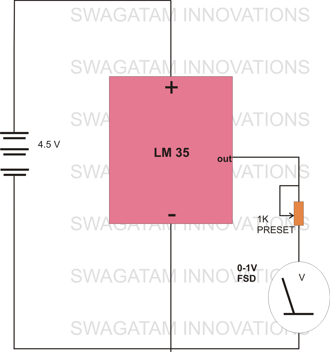
The circuit diagram provided illustrates a straightforward setup. There is no requirement for complex circuitry; simply connect a 0-1 V full-scale deflection (FSD) moving coil meter across the designated pins of the integrated circuit (IC). Adjust the potentiometer as...
The Battery Good checker. When the button is pressed, the green LED will glow if the battery voltage is above the preset threshold. This version has a higher parts count than the Battery Low version, but a bonus is...
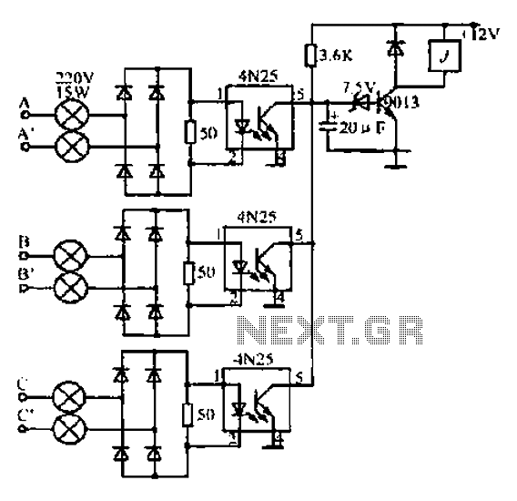
A, B, and C are used for a large power split-phase system. The A + BC range generator phase line features an A-A indole path string containing two 220V/15W bulbs. The bulbs recover based on macro instructions from J...
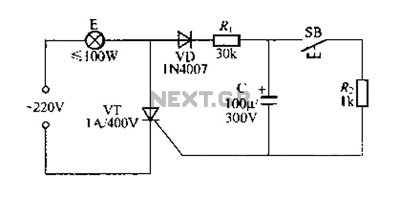
Figure 57 illustrates a simple delay lamp circuit that connects to lamp E using a two-wire connection. This design allows for the security bars to be installed directly, enabling replacement with a standard wall switch without altering the existing...
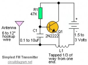
This is likely the simplest radio transmitter available. It comprises five components and can be assembled in a compact space. It is ideal for science fair projects or other science-related activities where short-range transmission is beneficial. The device operates...