
12V Battery Charger for Lead/Acid

The transformer winding for the charger supply is selected based on the charging voltage, plus the voltage drop across the regulator (3V), the rectifier drop (1.4V for two diodes), and an additional 10% for safety. For a 2V battery, the required AC winding is calculated as follows: 2V + 3V + 0.7V + 0.7V = 6.4V, plus 10% results in 7V. The charging current is limited by a small resistor in the common leg of the charger, with its value determined by the formula: R = 0.6V / maximum current. For a maximum current of 0.5A, the required resistance would be 0.6V / 0.5A = 1.2 ohms. The 0.6V represents the voltage necessary for the transistor to operate in full conduction. When the voltage is between 0V and 0.6V, the transistor adjusts the regulator to modify the voltage based on the current flowing through it.
The charging voltage can be adjusted using a potentiometer. A voltmeter should be connected to the charger (without the battery attached) to set the output voltage to the desired charging voltage. A 1K potentiometer is suitable for 2V batteries, while a 5K potentiometer is appropriate for 6V and 12V batteries. It is also advisable to include a fuse in the charger circuit, rated at approximately twice the maximum charging current. This fuse is crucial for safety, as batteries can discharge over 100 amperes during a short circuit, potentially causing significant damage or fires if a malfunction occurs in the charger. The fuse should be positioned after the regulator in the lead to the battery, serving to protect the rest of the circuit from the battery in case of a short circuit. Additionally, the primary winding of the charger should also be fused.
A diode placed across the regulator in the schematic protects the regulator from damage when the supply is turned off. In this scenario, the attached battery may provide a negative voltage across the regulator, as the output voltage exceeds the input voltage. The diode shorts the regulator in this case, preventing any potential issues. This diode serves as an additional safety measure.The battery charger circuit below is very simple to build requiring only a handful of cheap parts and an extra winding on your power tranny (or a separate tranny). Since the charger described is not active during sound reproduction, I have made no criteria on parts quality, so el-cheapo was the way to go.
There are many circuits available for char ging batteries, but many are for NiCd or NiMH batteries. They will not work for lead/acide batteries, so don`t use these! The best way to charge a battery is with a current limited voltage regulator. This sets a maximum current (say 1A) that will flow to charge the battery. If the current rises over this set current, the regulator will be forced to put out a lower voltage. Since voltage drops, so will the current; hence current limited. While the battery is charging, the current should decrease slowly while voltage starts to increase. In the end the current will be next to zero and the voltage will be equal to the set voltage. The charging current should be kept to around 0. 1 times the capacity of the battery. So a 10Ah battery should be charged with 1A of current (10 x 0. 1 = 1). The battery will not be forced (quick charged) this way and assures a longer lifetime. The transformer winding for the charger supply is chosen at the charging voltage plus 3V regulator drop plus 1. 4V rectifier drop (two diodes) plus 10% safety. So for a 2V battery, the winding (AC) is 2V + 3V + 0. 7V + 0. 7V = 6. 4V + 10% = 7V. The charging current is limited by the small resistor in the common leg of the charger. The value for this resistor can be calculated with: R = 0. 6V / max current. So if I want a maximum current of 0. 5A, I will need 0. 6V / 0. 5A = 1. 2 ohms. The 0. 6V is the voltage required for the transistor to go fully into conduction. Between 0V and 0. 6V the transistor will adjust the regulator to increase or decrease voltage depending on the current it is passing.
The charging voltage can be set using the potentiometer. Just hook up a volt-meter to the charger (without the battery attached) and adjust the output voltage until it macthes the charging voltage. Use a 1K pot for 2V batteries, use 5K for 6V and 12V batteries. Use an extra fuse on the charger, about two times the maximum current you are charging with. Fusing is critical for safety reasons. A battery can deliver 100+ amperes during a short, so it can cause serious damage or even fires when something goes wrong with the charger.
Put the fuse behind the regulator in the lead going to the battery. This fuse is not to protect the supply from a short in the charger, but to protect everything else from the battery in case of a short anywhere. Don`t forget to fuse the primary winding of the charger as well The diode over the regulator in my schematic prevents damage to the regulator when the supply is turned off.
In this situation the battery that is still attached offers a negative voltage over the regulator, as the voltage on the output is greater than the voltage on the input. The diode shorts the regulator in this situation and avoids any problems. It is just a safety. Source: Lead/acid battery charger 🔗 External reference
Related Circuits

The short in a Ni-Cad battery can be "burned off" with this zapper. The use of the SCR prevents heavy discharge current from damaging the switch contacts. More: follow the diagram. This circuit utilizes a zapper to eliminate shorts in...
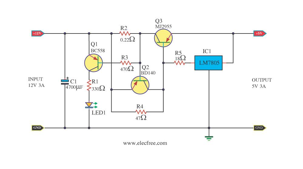
Today, a 12V to 5V 3A DC converter step-down regulator circuit has been presented. Sometimes, individuals have a 12V 3A power supply but require a 5V 3A output for digital circuits. This circuit fulfills that requirement by utilizing standard...
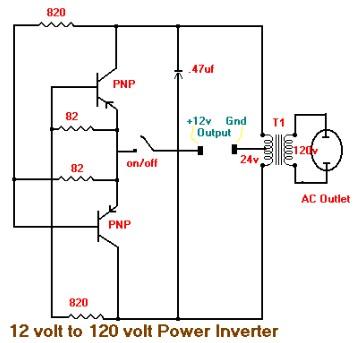
This is the schematic diagram of a 15W inverter circuit. The circuit is based on a PNP power transistor such as the TIP32 and other similar transistors. This inverter produces a square wave output, which may cause some noticeable...

The following diagram illustrates the circuit design of a Lead-Acid battery charger. This circuit provides an initial voltage of 2.5 V per cell at 25 °C to facilitate rapid charging of the battery. As the battery charges, the charging...
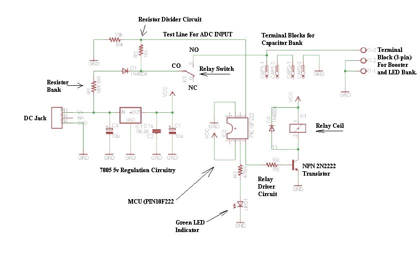
The schematic consists of four hardware blocks: 1) The wall transformer 2) The charging circuit 3) The control unit 4) The output stage. The circuit schematic is structured around four essential hardware blocks that facilitate the overall functionality of the...
This 6V to 12V converter circuit is made with an IC from SGS with several additional components. The IC is a TDA2003 but it can be replaced with a TDA2002. The cost of building the 6 volts to 12...