
499 Robot

The robot's architecture is modular, with a main controller at its core, which is an 18-pin, 8-bit PIC16F84 microcontroller. This microcontroller operates at a clock frequency of 4 MHz and is programmed using assembly language, allowing for efficient control of the various subsystems. The main controller interfaces with several modules including communication, drive, scoreboard, and motor driver circuits through its I/O pins.
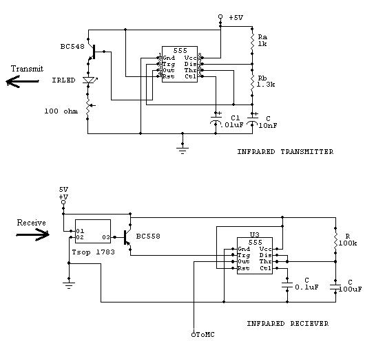
The communication subsystem includes a transmitter and receiver pair. The transmitter is managed by an 8-pin, 8-bit PIC12C509A microcontroller, also programmed in assembly language. The main controller sends control signals to the transmitter using two dedicated output pins—one for activating a laser and the other for enabling infrared transmitters. The laser generates a binary output that the opposing robot interprets as a hit, while the infrared transmitters can be toggled on and off based on the controller's commands.
The receiver employs a PNA4613M photo IC, which captures incoming infrared signals and sends the corresponding bit stream back to the main controller through an input pin. The main controller processes this data and generates appropriate responses based on the received signals.
For scorekeeping, the scoreboard is also driven by an 8-pin, 8-bit PIC12C509A microcontroller, which is connected to the main controller via a continuously polled input pin. The main controller can increment the score display by toggling this input pin high.
Motor control is facilitated by the L293D dual H-bridge driver IC, which is essential for driving the robot's motors. Each motor is controlled by two logic signals from the microcontroller, allowing precise direction control.
To monitor battery status, a Low Battery Indicator circuit is implemented using an LM741 operational amplifier configured as a comparator. A zener diode establishes a reference voltage at the non-inverting input, while a voltage divider connected to the battery voltage feeds into the inverting input. When the voltage drops below the reference, the comparator output triggers a red LED, indicating low battery conditions.
Charging of the robot's sealed lead acid (SLA) batteries is managed by a charger designed around the UC3906 battery charge controller IC. This charger operates as a dual-level float charger and features temperature compensation to optimize performance based on the battery's temperature characteristics, ensuring longevity and reliability in operation.The robot consists of modules controlled by a main controller. The main microcontroller is an 18-pin, 8-bit, PIC16F84 Flash microcontroller operating at 4MHz. The microcontroller is programmed in assembly language. The controller is connected via I/O pins to the communication module, drive module, scoreboard and the stepper motor driver circuit. T he controller is responsible for processing the input received from the receiver module and executing the necessary responses. The transmitter is controlled by an 8-pin, 8-bit PIC12C509A microcontroller programmed in assembly language.
The main controller outputs control signals to the transmitter via two output pins. One pin controls the laser and the other enables the infrared transmitters. The output from the laser is a stream of bits decoded by the opposing robot as a hit. The output to the infrared transmitters allows the transmitter to be turned on and off by the controller. The receiver is a PNA4613M photo IC. The controller receives input signals from the receiver module via an input pin. The data sent by the receiver module is a stream of bits corresponding to the infrared signal received.
The controller processes the signal and responds to valid data received. The scoreboard is controlled by an 8-pin, 8-bit PIC12C509A microcontroller. The microcontroller is programmed in assembly language. The scoreboard connects to the main controller via an input pin. The input pin is polled continuously. The main controller toggles the input to the scoreboard high to increment the hit count on the score display. The L293D is a dual h-bridge driver IC. The IC is also referred to as a push-pull four channel driver. An h-bridge is ideal for driving motors. The L293D provides two h-bridges for driving both motors on the robot base. The motor direction is controlled by logic signals from the microcontroller. Two signals per motor are required to control the direction The Low Battery Indicator circuit was designed with the availability of parts, and low cost in mind.
The circuit is based to the LM741 operational amplifier. The op amp is configured as a comparator. A zener diode provides a voltage reference to the non-inverting input of the comparator. A voltage divider between the battery voltage and ground is connected to the inverting input. When the voltage of the divider drops below the reference voltage then the output of the comparator goes low and lights a red LED (tied high). Charging of sealed lead acid (SLA) batteries has a significant effect on the performance and service life of the battery.
The charger developed for the robots` SLA batteries was designed to meet the specifications of the battery as given above. The charger design is based on Unitrode`s UC3906 battery charge controller IC. The charger is a dual-level float charger. An important feature of the UC3906 is that it is temperature compensated to track the battery temperature coefficient.
🔗 External reference
Related Circuits
One of the students has created a robot that utilizes two stepper motors and a simple IR sensor. The robot, which is depicted in the accompanying image, has some issues such as a lack of battery support and misalignment...
For a robot to perform its assigned tasks, a controller is necessary. This controller may be mechanical, electrical, electronic, or a combination of these. It acts as the brain of the entire system, providing the robot with its intelligence....
This page contains links to various projects and items of interest for the RoboticsArt Studio class projects. The RoboticsArt Studio class projects encompass a range of innovative endeavors that integrate art and robotics. These projects typically involve the design, assembly,...
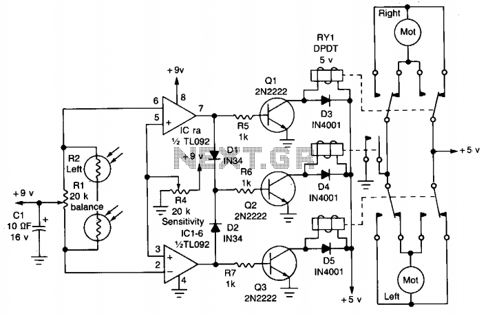
The circuit is designed to seek light, allowing a robot to follow a flashlight in a dark room. Two photocells are used to determine the direction of the robot's movement. Each photocell is connected to an operational amplifier configured...
Lectures on line following robots consist of multiple sessions, including Lecture 1 (a), Lecture 1 (b), and Lecture 1 (c). A concept diagram is provided for a 1 cm line following robot, along with a schematic for a robot...
The strategy focused on efficiently navigating complex terrain with superior speed. The objective was to score in the lowest scoring goal by acting quickly to limit the opposing team's points. The mechanical and electrical designs prioritized speed, resulting in...