
Hextor Hexapod Robot

The electronic circuit features a comprehensive arrangement of connections tailored for a BOS processor and peripheral devices. The design begins with the serial communication lines, where pin 0 is configured as the transmit (TX) line to send data to the BOS processor, while pin 1 serves as the receive (RX) line for incoming data. This dual-channel communication is essential for effective data exchange between the processor and other components.
Power management is handled through pin 2, which is connected to a power supply. When this pin is set high, it activates the power to the entire electronic system, ensuring that all components receive the necessary voltage to function. Conversely, pin 3 acts as a control line to halt current flow; when activated, it effectively disables the circuit, which can be crucial during debugging or maintenance.
The circuit also incorporates a busy signal indicator via pin 4. This pin is monitored to determine if the BOS processor is currently engaged in processing tasks. A high signal on this pin indicates that the processor is busy, allowing other components to synchronize their operations accordingly.
For communication with infrared devices, pin 5 is utilized as an input for receiving infrared signals. This feature enables the circuit to interact with remote controls or other infrared communication devices. Data transmission to an LCD is facilitated through pin 6, which sends commands or information to the display, while pin 7 is dedicated to receiving feedback or data from the LCD, ensuring a bidirectional communication link.
LED indicators are integrated into the circuit for visual feedback. Pin 8 controls a right green LED, which illuminates when the pin is set high, signaling a positive state or action. Similarly, pin 9 operates a left red LED, providing a contrasting indication. These visual cues are essential for user interaction and system status monitoring.
Lastly, the circuit incorporates ultrasonic communication capabilities. Pin 14 is designated for transmitting ultrasonic commands, while pin 15 is set up to receive incoming ultrasonic data. This functionality enables the circuit to perform distance measurement tasks or object detection, further enhancing its application scope.
Overall, this circuit configuration presents a robust framework for integrating a BOS processor with various peripherals, facilitating effective communication, power management, and user feedback through visual indicators.circuit multiprogs 1 BOS tx con 0 `pin serial to BOS processor 0 BOSrx con 1 `pin serial from BOS processor 4 epower con 2 `pin high turns on power to electronics 2 BOShalt con 3 `pin high halts current BOS move 3 BOSbusy var in4 `pin BOS processor busy => high 5 irrx con 5 `pin infra red comms in, i96n 6 lcdtx con 6 `pin to send to LCD 7 lcdrx con 7 `pin to receive from LCD 8 Rled con 8 `pin high turns on right green led 9 Lled con 9 `pin high turns on left red led outRled var out8 `pin high turns on right green led outLled var out9 `pin high turns on left red led 14 ustx con 14 `pin ultrasonic commands, i96n 15 usrx con 15 `pin ultrasonic data in, i96n 🔗 External reference
Related Circuits
Construct a low-cost and relatively simple robot that activates whenever a desk lamp is illuminated. The design does not incorporate any sensors. This robot can be designed using basic electronic components to create a simple activation mechanism based on light...
Wireless power transfer is not a new concept; it has been discussed since Tesla's patent in 1900, titled "Apparatus for Transmission of Electrical Energy" (USPTO #649, 621). As the technology evolves, the range of potential applications will expand. For...
A prototype model of an agriculture-based robot has been developed to address the challenges faced by farmers who have traditionally relied on manual labor for cultivating their lands. The increasing urbanization has led to a shortage of labor, as...
The objective of the project is to develop a robot capable of following a black line on a white sheet of paper and navigating through a maze constructed from these materials. The maze specifications include black lines with a...
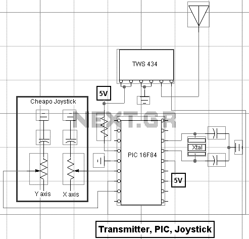
With a handful of inexpensive components, a little creativity, and the power of PicBasic, you can build some pretty outstanding robotics creations as Rob Arnold proves with his Ruf-Bot project. RF remote control is just way too cool not...
The strategy focused on efficiently navigating complex terrain with superior speed. The objective was to score in the lowest scoring goal by acting quickly to limit the opposing team's points. The mechanical and electrical designs prioritized speed, resulting in...