
Stereo headphone amplifier
The headphone amplifier circuit described utilizes dual LM386 integrated circuits to amplify audio signals for headphone listening. Each LM386 operates as a low-voltage audio power amplifier, providing sufficient gain for a variety of audio sources. The circuit is designed for stereo output, with each channel mirroring the configuration of the other.
The input stage of the circuit includes a dual potentiometer (R1A) that functions as a variable input attenuator, allowing for volume control across both channels simultaneously. Capacitor C2 serves to couple the audio input signal while R2 isolates it from the potentiometer, ensuring that the signal integrity is maintained. High-frequency noise is mitigated by capacitor C1, which bypasses unwanted frequencies to ground, while capacitor C3 stabilizes the inverting input of the LM386.
Power supply stability is crucial for audio applications; therefore, resistors R3 and R4, along with capacitors C4 and C6, provide bypassing to ensure clean power delivery to the amplifiers. The output stage is similarly configured with capacitors C7 and C8, which couple the amplified audio signal to the headphone output while filtering out any residual noise.
For applications requiring a tailored frequency response, particularly with guitar signals, additional components (C5, R5, C6) can be added to adjust gain and frequency characteristics. This allows the amplifier to better accommodate the specific needs of electric guitar signals, which often have a different impedance and frequency profile compared to typical line-level audio sources.
The construction of the circuit can be accomplished on a perf board or a custom printed circuit board (PCB), with layout diagrams provided for ease of assembly. Consideration should be given to component quality, particularly the use of low-leakage capacitors and metal-film resistors, to maximize the performance and fidelity of the headphone amplifier.
Enclosure design plays a significant role in the overall performance of the amplifier. A steel enclosure is recommended for optimal electromagnetic shielding; however, bakelite project boxes are also suitable, offering durability and aesthetic benefits. Proper mounting of RCA jacks and securing them with silicone sealer are essential to ensure longevity and reliability in the assembly.The ping of the cymbals, crack of the snare drum, thonk of the bass - none of these comes through on my low-budget speakers. Sometimes they sound so fuzzy I want to hide behind the couch until it’s over. But headphones...ah, heaven! There are probably as many headphone amp designs as there are headphones, but all aren’t created equal.
The cheesy headphone-amp circuits in most stereo gear aren’t up to the standards of the main amp components, and many CD players and cassette decks don’t even have them. This do-it-yourself stereo headphone amp sounds clean and clear, and uses just two, inexpensive chips.
It’s great for practice, multitrack monitoring, or just plain listening as a receiver/integrated-amp substitute. he circuit gets its zip from two National Semiconductor LM386 Low Voltage Audio Power Amp ICs, one for each side of the stereo path. The left and right channels are identical. Refer to the schematic, Fig. 1, using the left channel as a guide. Dual potentiometer R1A serves as variable input-attenuator (the dual pot controls both channels); R2 isolates C2, which capacitively couples the input.
Cl bypasses high-frequency input noise to ground; C3 bypasses the inverting input. R3 and C4 bypass the power supply. R6 and C7 bypass the output; C8 capacitively couples it. The LM386 is internally configured to provide a gain of 26 dB: this is a bit too much for line-level inputs. R4 reduces the gain by -6 dB. If you want to tailor the response for guitar signal input, you will have to add some additional components (indicated with dotted lines), because the guitar output is a low-voltage signal with a predominance of high frequencies.
C5 (which substitutes for the indicated jumper) rolls off the high frequencies at -6 dB/octave, with a cutoff frequency of about 5kHz. R5 and C6 provide about +6dB of gain recovery to boost the signal. The sound quality you’ll get from your headphone amp will be directly proportional to the quality of the passive components it incorporates.
Use the best poly and low-leakage electrolytic capacitors you can obtain. Metal-film resistors help maximize the signal-to-noise ratio, though I’ve had good results with carbon-film types. Perf-board construction is fine. If you want to make your own PC board, Fig. 2 shows a full-size, 1:1 pattern, and Fig. 3 shows the parts layout. If you intend to use the headphone amp solely with guitar, add the optional components indicated with the dotted lines (C5.
R5, C6, C13, R10, C14, and the mono switch). Pads are provided on the PC layout. For line-level applications (synth, tape, CD, etc.), omit these components and install jumpers across the C5 and C13 locations, as indicated. Note that guitars feeding effects, active guitar pickups. and even some passive pickups are hot enough to drive line inputs. A steel enclosure will provide the best shielding; however, I installed a dozen headphone amps in bakelite project boxes, as shown at the beginning of this article, with good results.
Aesthetics aside, bakelite boxes offer several advantages: you don’t have to paint them; they’re fairly impervious to the occasional spilled beverage; and if they get dirty, you can just wipe them off. I had the ID plates (VOL, PHN, L, R) made at a local shop that engraves name tags, and glued them on with Scotch 6004 Super Strength Adhesive.
This method of labeling is much more durable than using rub-on letters covered with a lacquer finish. Since the RCA jacks mount through the case front, they have to be wired in place. With this type of enclosure, it’s easiest to attach the leads to the board first. then solder to the jacks, with the board not yet mounted. RCA jacks have a tendency to work loose; to secure them, squirt some silicone sealer around the jack-nuts.
🔗 External reference
Related Circuits
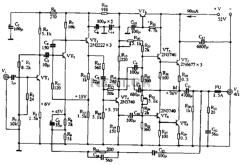
The circuit depicted in the figure is a highly technical OTL (Output Transformer-Less) amplifier circuit. It features a frequency response range of 10 Hz to 100 kHz and exhibits a total harmonic distortion of less than 0.1%, which is...
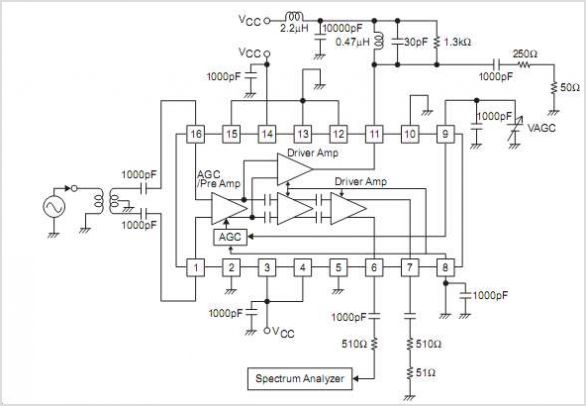
The LC72146 is a Phase-Locked Loop (PLL) Frequency Synthesizer LSI circuit designed for electronic tuning in car stereo systems. This component facilitates the development of high-performance, multifunctional electronic tuning systems across VHF, MW, and LW bands. It is manufactured...
Construct an accurate LC Meter (Capacitance Inductance Meter) to facilitate the creation of coils and inductors. This LC Meter is capable of measuring very small inductances, making it an ideal tool for various RF coil and inductor applications. The...
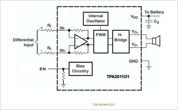
The TPA3007D1 is a 6.5-W mono bridge-tied load (BTL) class-D audio power amplifier featuring high efficiency, which eliminates the need for heat sinks. This amplifier can drive 8-ohm speakers with only a ferrite bead filter required to reduce electromagnetic...
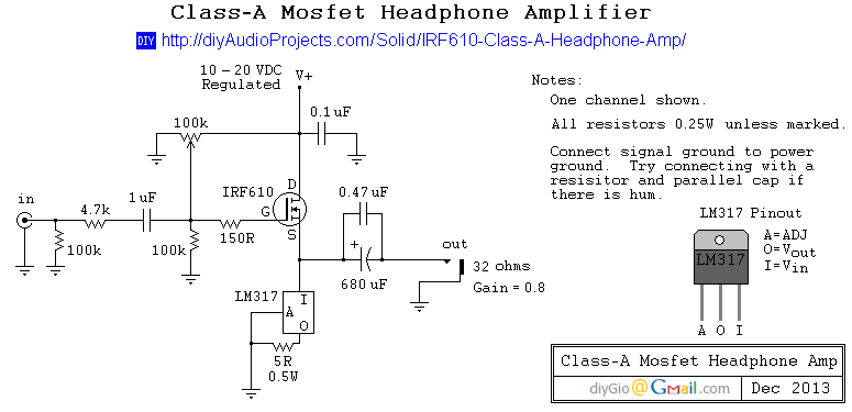
This is a simple and low-cost desktop headphone amplifier designed for office use. The amplifier concept is straightforward and adheres to a typical single-ended Class A circuit. The desktop headphone amplifier utilizes a single-ended Class A design, which is known...
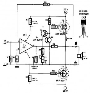
This audio power amplifier employs two complementary MOSFETs (IRF9520 and IRF520) to provide up to 20W output into an 8-ohm speaker. A TL071 operational amplifier functions as the input amplifier. The MOSFETs require heatsinking with a thermal resistance of...