
Scramble phone

The circuit described involves an integrated circuit (IC-1) that functions as a stable audio tone generator. This generator produces a consistent audio frequency output, which is then buffered by two transistors, Q1 and Q2. The output from these transistors is taken from their emitters, providing a reliable carrier voltage for the balanced modulator circuit composed of four diodes (D1 to D4) and two transformers (T1 and T2).
In an ideal scenario where all components are perfectly matched, the balanced modulator would not produce any carrier signal at either the input or output of the transformers. However, in practical applications, slight mismatches between the components are inevitable, leading to the generation of a low-level carrier tone that can be observed at both the input and output of the modulator.
The circuit also incorporates a telephone carbon microphone connected to the low impedance winding of transformer T1. This microphone requires a three-volt battery to provide the necessary current for operation. The trim potentiometer R4 is an essential component for fine-tuning the oscillator frequency, enabling synchronization between two scrambler units to operate at the same carrier frequency. Additionally, resistor R6 is included in the design to limit the line current to a maximum of 25 mA, ensuring that the circuit operates within safe current levels and preventing potential damage to the components.
Overall, this circuit design is crucial for applications requiring audio tone generation and modulation, particularly in communication systems where synchronization and stability are paramount.IC-1 and the associated circuitry form a stable audio tone generator that feeds a buffer amplifier, Ql and Q2. The tone output is taken from the emitters of the transistor pair to supply a carrier voltage for a balanced modulator made up of four diodes—Dl through D4—and Tl and T2.
If the two transformers and the four diodes are perfectly matched (which is almost impossible to achieve and not necessary in any case) no carrier will appear at the input or output of Tl or T2. In a practical circuit, a small amount of unbalance will occur and produce a low-level carrier tone at the input and output of the balanced modulator. A telephone carbon mike and earpiece are connected to the low impedance winding of 1, with a three volt battery supplying the necessary mike current.
Trim potentiometer R4 is used to make a fine frequency adjustment of the oscillator so that two scrambler units may be synchronized to the same carrier frequency. Rg limits line current to 25 mA.
Related Circuits
This preamplifier amplifies the signal from a microphone, an amplifier so that it can be further strengthened. The circuit supplies an output signal line. With two transistors, it is not difficult to build such a circuit. The amplifier produces...
This is a design for a low noise microphone preamplifier, which is ideally suited to low impedance (600 Ohm nominal) microphones. One limitation is that it is not balanced, which is not a problem in a home recording environment,...
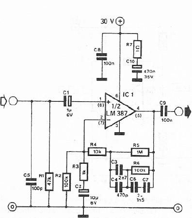
A dynamic microphone preamplifier can be constructed using the LM387 dual operational amplifier integrated circuit. The input impedance is approximately 47k ohms, primarily determined by resistor R1. If a dynamic microphone with a different impedance is to be connected,...
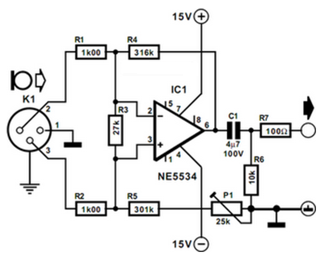
The preamplifier is designed for use with dynamic (moving coil MC) microphones with an impedance of up to 200 ohms and balanced terminals. It features a straightforward design and can be regarded as a single-stage instrument amplifier utilizing a...
Many cordless phones are still analogue and use the frequency from 30-50MHz. The signal is FM-modulated and can easily be picked up with any FM receiver. An FM receiver that can be adjusted within this frequency range is presented....
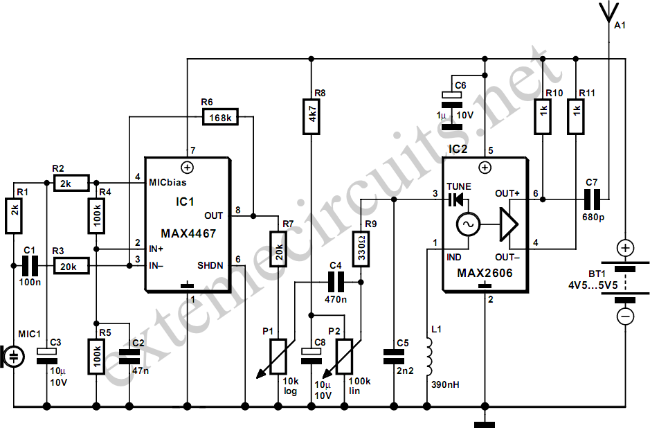
This project is a simple, inexpensive, and engaging circuit designed for home experimenters or hobbyists. It functions as a basic transmitter capable of transmitting speech over a short distance, effectively serving as a cordless microphone. The circuit employs two...