
Undervoltage delay tripping a circuit
Undervoltage release mechanisms are essential for protecting electrical circuits from damage caused by prolonged low voltage conditions. The operation principle is based on monitoring the supply voltage and activating a release mechanism when the voltage falls below a predetermined threshold. This is critical for ensuring the safety and reliability of electrical systems.
In the case of instantaneous tripping, the circuit breaker disconnects immediately upon detection of undervoltage, minimizing the risk of equipment damage. On the other hand, the tripping delay feature allows for temporary voltage fluctuations without immediate disconnection, which can be beneficial in scenarios where brief dips in voltage are common.
The electronic trip unit typically incorporates microcontroller-based technology that continuously monitors the voltage levels and can provide precise control over the tripping characteristics. This allows for programmable settings based on specific application requirements.
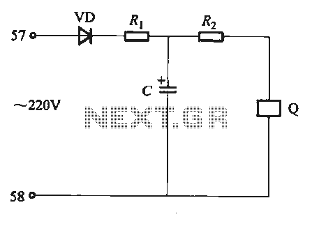
In contrast, the resistive-capacitive delay release circuit employs passive components to achieve the desired delay. The resistor (Ri) and capacitor (C) form an RC time constant that determines how quickly the circuit responds to undervoltage conditions. By adjusting the values of these components, the delay time can be fine-tuned to suit the needs of the application. The coil (Q) activates the tripping mechanism when the voltage across the capacitor drops below a certain level, effectively cutting off the breaker and protecting the circuit.
Overall, understanding the functionality and configuration of undervoltage release systems is crucial for electrical engineers and technicians involved in the design and maintenance of reliable power distribution systems.Undervoltage release is long-term work, when the power supply voltage drop in the operating voltage range when the release is released, and directly led to the tripping axle rotation, cut off the breaker. Undervoltage release Instantaneous tripping points and tripping delay two species. Which reached the undervoltage delay trip there two ways kinds: one is the electronic trip unit (see Figure 6-81); the other one is the resistive capacitive delay release, the line shown in Figure 6-84 FIG. FIG, Q is undervoltage release coil. Adjustment capacitor C and a resistor Ri, the parameter value of R2, can change the delay time.
Related Circuits
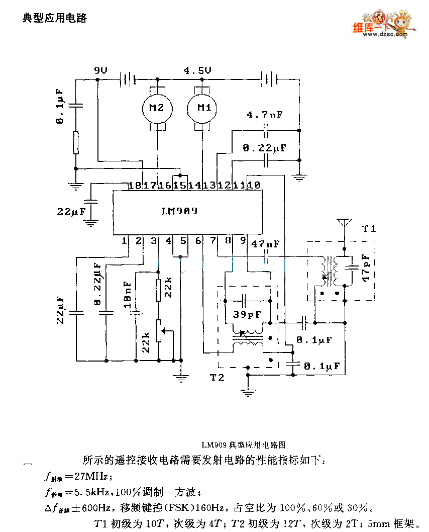
The performance indices of the telecontrol receiving decoding circuit are as follows: radio frequency (f) = 27 MHz, audio frequency (f) = 5.5 kHz, 100% modulation in square-wave form; radio frequency deviation is ±600 Hz, and the frequency shift...
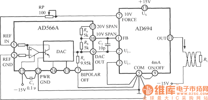
The current loop interface circuit diagram of the AD694 multi-functional sensor signal conditioner is utilized as a digital-to-analog converter (DAC). This current loop interface enables the conversion of digital values into voltage and subsequently into current signals. The circuit...
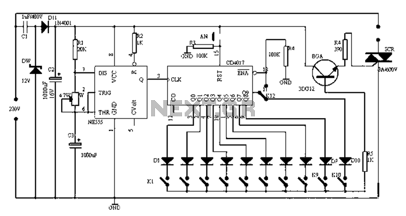
Figure 1-1 illustrates a general-purpose timer capable of timing intervals ranging from 5 minutes to 18 hours. The timing cycle can be adjusted to span from 5 minutes to 20 hours, with a maximum control time of 18 hours....
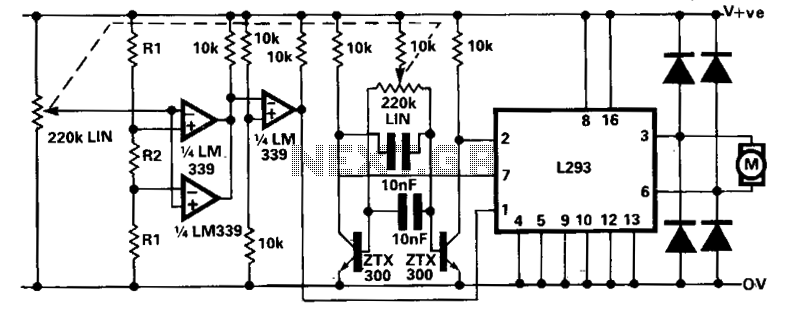
A limitation of the bi-directional proportional motor control circuit is that when the potentiometer is in its center position, the motor does not stop but continues to creep. This occurs due to the challenge of precisely adjusting the potentiometer...
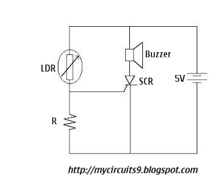
The Light Dependent Resistor (LDR) is a variable resistor whose resistance decreases as light intensity increases. Under normal light conditions, the resistance of the LDR is sufficiently high, resulting in an inadequate voltage across resistor R to activate the...
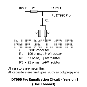
2 versions of the equalization circuit, the first having 6 dB less insertion loss than the other. However, some may not be able to find a 0.68 microfarad capacitor. The second version uses a more common 0.22 microfarad capacitor....