
Modular Music Box
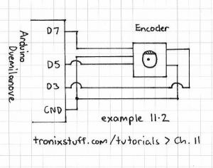
The circuit design involves the integration of a quadrature encoder, which provides two output signals (A and B) that indicate the direction and amount of rotation. The encoder's push button will be connected to a microcontroller, which will utilize the DebounceButton library to handle the button press events reliably. The RSet resistor is crucial for setting the correct current through the LEDs; thus, accurate calculations based on the intended application (individual LEDs versus an LED matrix) are necessary to avoid inconsistencies in brightness and performance.
Incorporating a common ground for the I2C bus is essential for ensuring stable communication between multiple devices. The rotary sequencer box will likely house both the encoder and the necessary circuitry to maintain this common ground. The design must account for the potential contact bounce from the encoder's push button, necessitating software debouncing techniques to ensure that only valid button presses are registered. This will involve implementing additional logic within the microcontroller's firmware to differentiate between actual button presses and noise caused by mechanical bouncing.
Furthermore, attention should be given to the power supply stability and noise filtering, especially in environments where multiple components share the same ground. Capacitors may be employed near the power pins of the microcontroller and the encoder to smooth out any fluctuations. Overall, careful consideration of the components, their specifications, and the interaction between them will lead to a robust and functional design for the intended application.I calculated the RSet resistor value at ~17k though it should probably have been 28k according to the table on the page (the MV7744 data sheet list Vf = 2. 1V and If = 20mA) but that`s for an LED matrix not individual LEDs happy for you to work out what this should be .
Used Keith Neufeld`s Arduino Quadrature Encoder Library available here to download and though initially it didn`t compile reading further in the post I came across instructions to add: Also intending to use quistoph`s DebounceButton Arduino library (link currently not working) to provide onPress(), onRelease, onHold(), onClick() functionality which combined with the push button of the encoder could be useful as a hidden` control system should we need it My colleague Nick discovered the requirements for a common ground for the I2C bus so we`ll need to plan this into the circuitry of one of the boxes probably the rotary sequencer The problem is first that they have a lot of contact bounce and trying to suppress this in software and determine the direction of rotation at the same time is a bit of a big ask and normally it won`t work. I don`t know if you noticed but some times the Project sketch would go in the wrong direction at times.
🔗 External reference
Related Circuits
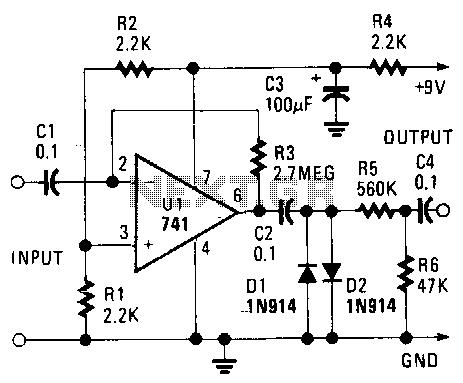
The maximum gain of the 741 operational amplifier, which is typically 20,000, can be increased to nearly 3 million dB, resulting in output distortion. This distortion produces a fuzz sound. Additionally, the signal level is reduced by clipping through...
The circuit is based on a single operational amplifier integrated circuit designed to produce a modular preamplifier that operates in Class A configuration. The modular preamplifier circuit utilizes a single operational amplifier (op-amp) integrated circuit, which serves as the primary...
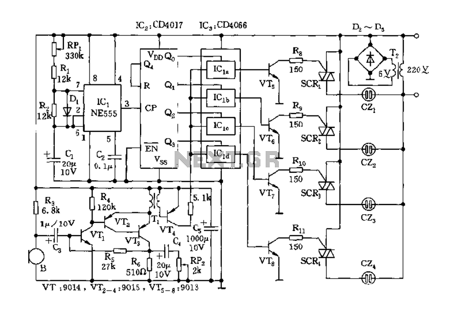
The circuit includes a controller that integrates an acoustic-electric conversion and amplification circuit, a clock pulse generator, a counting circuit, and a control circuit. It manages four accompanying music tracks and flashing lights. Microphones (MIC) convert sound into electrical...

A resistive voltage divider is utilized to establish a bias voltage for the input pins (Pins 2 and 3). The demodulated frequency modulation (FM) signal is introduced to the input via a two-stage high-pass filter, which serves to provide...
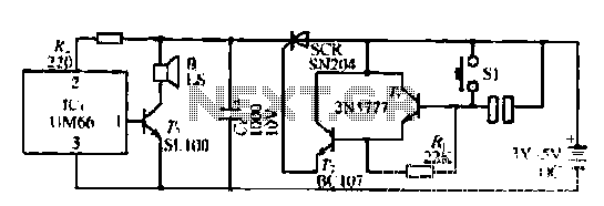
A few custom integrated circuits began to play music. When the song ends, no electricity flows through the thyristor, which then cuts off the light, causing the phototransistor to activate. The system is designed with a touchpad; each touch...
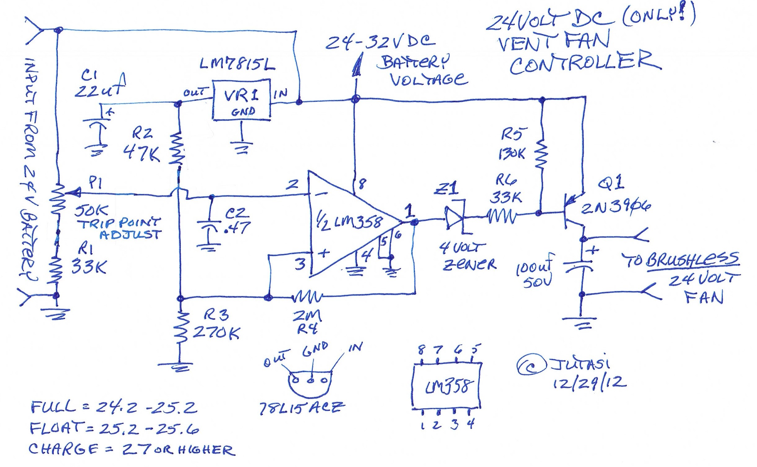
One of the backup systems utilizes a Magnum MS-PAE 4024 inverter, which lacks a built-in fan controller. Since batteries emit hydrogen during both normal and equalization charging, it is crucial to ventilate the batteries to the outside using a...