
Pest Repeller Circuit
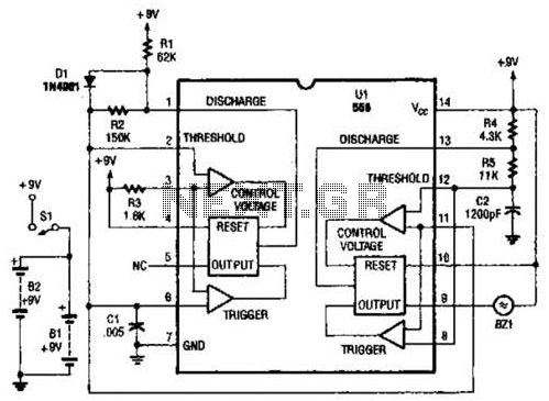
The bug repeller circuit utilizes two distinct timer configurations, each contributing to its overall functionality. The left oscillator, characterized by its 50% duty cycle, generates a square wave signal where the on-time is equal to the off-time. This balanced duty cycle is essential for producing a consistent frequency output, which can be adjusted by altering the external resistors and capacitors connected to the timer. This configuration ensures that the bug repeller emits a stable signal that can effectively disrupt the behavior of insects.
In contrast, the right oscillator operates as a voltage-controlled oscillator (VCO). This type of oscillator allows the output frequency to be modulated based on an input voltage. By varying the control voltage applied to the VCO, the frequency of the output signal can be dynamically adjusted. This feature adds versatility to the bug repeller, enabling it to adapt its frequency to target different types of pests or environmental conditions.
Both oscillators are integral to the operation of the bug repeller, allowing it to generate ultrasonic frequencies that are unpleasant to insects while remaining inaudible to humans. The external threshold settings for both timers provide a means to calibrate the circuit for optimal performance, ensuring that the emitted frequencies are effective in deterring pests while minimizing potential interference with other electronic devices. The design of the circuit emphasizes flexibility and adaptability, making it a practical solution for pest control applications. The two timers in the bug repeller have some interesting characteristics. Roth of them have their thresholds externally set; the oscillator on the left has a 50% duty cycle and the oscillator on the right acts as a VCO. 🔗 External reference
Related Circuits
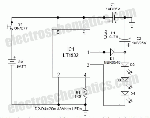
This circuit features a portable solid-state bright light utilizing the LT1932 integrated circuit. It can be powered by two AA dry or rechargeable pen-light batteries. The design allows for customization of the housing, enabling various applications such as a...
This LED circuit replicates the initial LED sequence currently utilized by FISA for Formula One racing. It can also be employed with slot car sets, such as HO scale AFX, Life Like, or Tyco sets, or used in communication-controlled...
This project is suitable for individuals who enjoy experimenting with electronics. It presents a low risk of damaging the unit. This project involves creating a simple electronic circuit that allows users to engage in hands-on experimentation without significant risk. The...
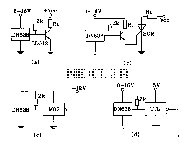
Figures (A), (B), (C), and (D) illustrate outputs that can directly drive transistors, thyristors, relays, CMOS circuits, and TTL circuits. The described figures depict various output configurations capable of interfacing with different electronic components. Each output is designed to provide...
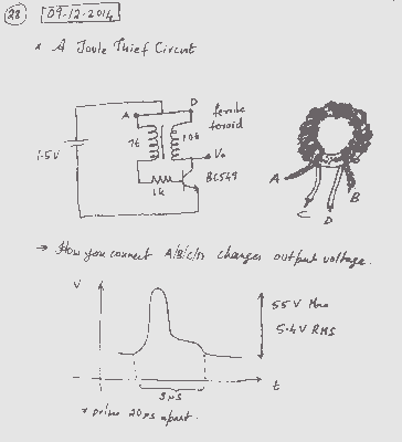
A simple voltage boost circuit known as the Joule Thief has been identified for construction. The Joule Thief is a minimalist boost converter designed to extract energy from low-voltage sources, such as depleted batteries, and increase the voltage to a...
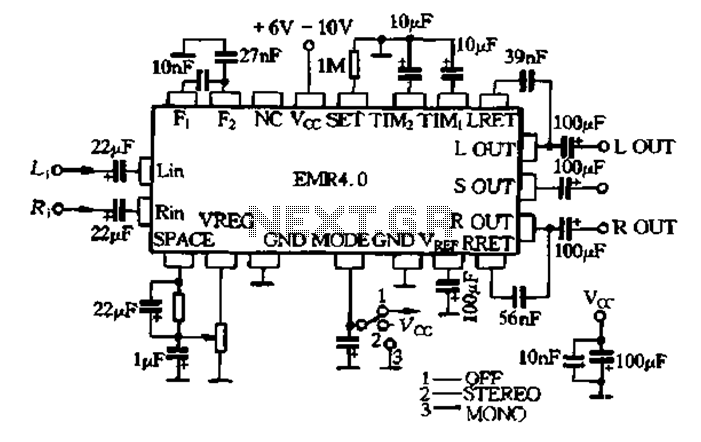
The EMR 4.0 operates with a single power supply ranging from 6V to 10V, with an optimal supply voltage of 9V. It requires effective power filtering to minimize noise, particularly when there is no signal input. The quiescent current...