
Momentary Switch Teamed With Latching Relay
The circuit operates with a straightforward mechanism that allows for efficient control of the relay using minimal components. The SPST momentary pushbutton serves as the primary input, initiating the switching action of the relay. The DPDT relay is crucial for achieving the latching functionality, maintaining the last state until the pushbutton is pressed again. The use of capacitors C1 and C2 is essential for timing and energy storage, with C2 facilitating the initial switching and C1 ensuring the relay remains in the desired state until the next activation.
Resistor R1 and R2 play pivotal roles in controlling the charging rates of capacitors C1 and C2, respectively. The values of these resistors can be fine-tuned to optimize the circuit's response time and power consumption characteristics. The diode D2 is included to prevent back EMF generated by the relay coil from damaging other components in the circuit, ensuring reliable operation over time.
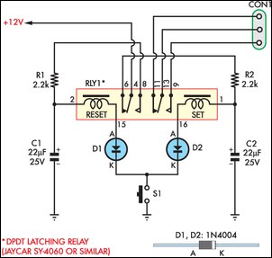
This design is particularly suited for applications where a momentary switch is preferred for toggling power to devices or systems, such as in automotive or industrial settings. The ability to adapt the circuit for different relay specifications allows for versatility in implementation, accommodating various power requirements and operational conditions. Overall, this circuit exemplifies an efficient and effective solution for push-on push-off switching applications.This circuit allows an SPST momentary pushbutton to act as a push-on push-off switch, using a DPDT latching (bi-stable) relay. It was originally intended to allow a single pushbutton switch on the dash of a vintage car to provide a latched function.
The relay only draws current when it is being switched. At other times, the only current drain on t he 12V supply is the leakage current of one 22 µF capacitor, which is very low. It works as follows. Assume that initially the latching relay is in the reset state, with pins 4 and 6 connected together. In this state, C2 charges up to +12V via 2. 2kO resistor R2 while capacitor C1 remains discharged as it is not connected to the 12V supply. If S1 is pressed, C2 discharges via the relay`s set coil, diode D2 and S1. This switches the relay into its set position, connecting pins 4 and 8. C1 then begins to charge via R1. While S1 is being held down, the relay does not return to the reset position because the current supplied via R1 is insufficient for the coil to latch the armature.
As soon as S1 is released, current no longer flows though the coil so C1 can finish charging, ready for the next button press. Once the relay has switched and C1 has finished charging, pressing S1 again causes the relay to switch back to the reset state via the same process.
The unused set of relay contacts can be used as an SPST or SPDT switch. The circuit as shown has been tested with the Jaycar SY4060 relay. It will work with other DPDT twin-coil latching relays but the resistor and capacitor values may need to be adjusted to suit. Relays with lower resistance coils will need larger value capacitors and smaller value resistors. 🔗 External reference
Related Circuits

This is an extension of the CMOS toggle flip flop circuit shown in the Circuits controlling relays section with the addition of two bandpass filters and condenser microphone so the relay can be toggled by whistling at it. The...
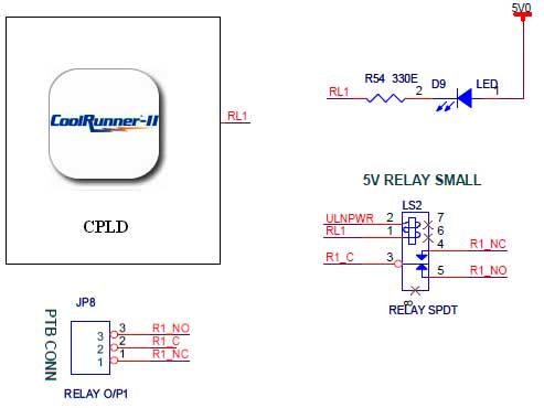
The CoolRunner-II board features external 5V relay interfacing, as indicated in the accompanying figure. The ULN2803 is utilized as a driver for the CPLD I/O lines, with the driver outputs connected to the relay modules. A PTB connector is...
This project describes how to build a "soft touch" switch. By "soft touch" we mean that you have to push once to set device ON and push again to set device OFF. This kind of switch works by latching...
While many power supplies can be set to limit their output current to a defined level to protect the circuit they are powering, no such protection is available. To enhance the safety and reliability of electronic circuits, it is crucial...
Do you have a bicycle? Why not try to build this circuit? It is powered by a 3-6V battery. This circuit will assist the bicycle rider at night and alert others to their presence. The switched-on bike lamp circuit...
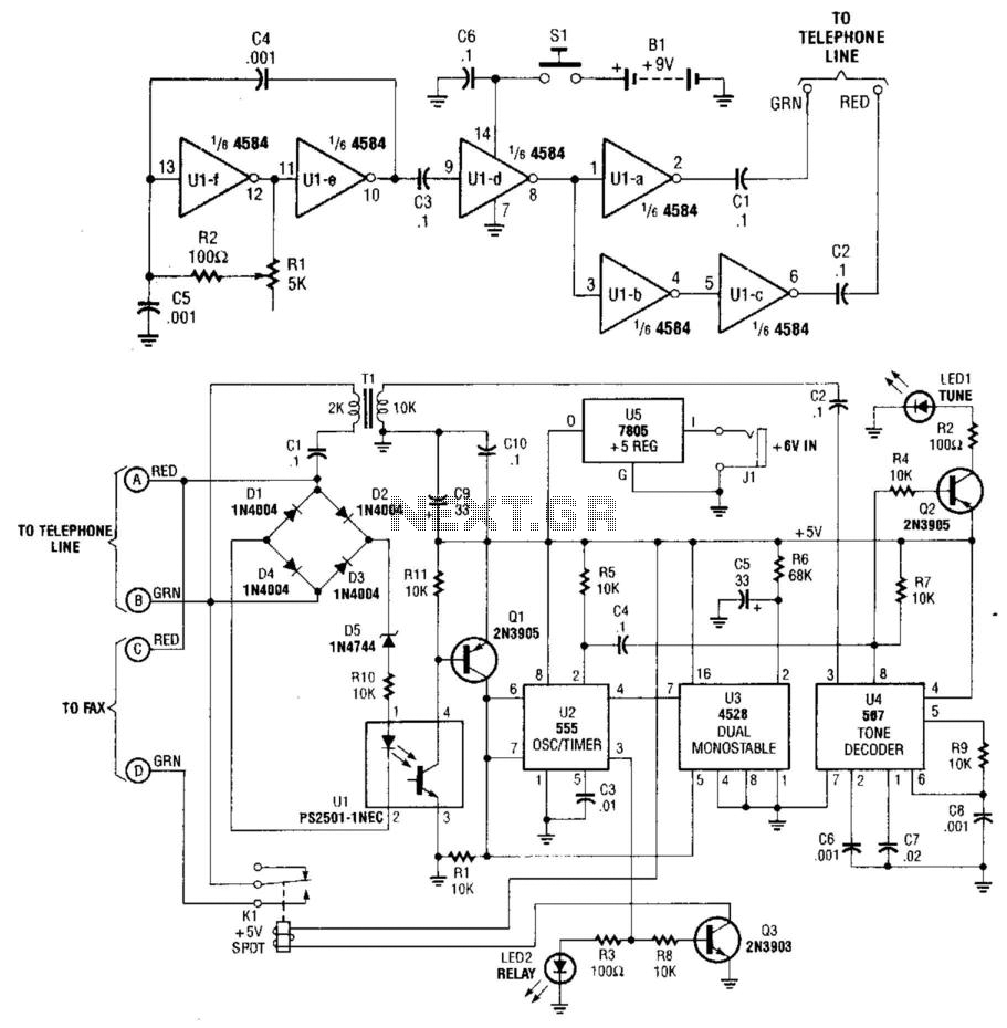
This system uses a transmitter operating at approximately 100 kHz to control a remote receiver. A line splitter can connect the transmitter to the active telephone line. The transmitter is a CMOS oscillator equipped with output buffer stages to...