
Switched Bike Light
The sound-activated light functions by utilizing a condenser microphone positioned to capture sound, generating AC signals. These signals pass through a DC blocking capacitor (C1) to the base of transistor BC549 (T1). Transistors T1 and T2 amplify the sound signals and produce current pulses at the collector. Light Emitting Diodes (LEDs) are noteworthy components, as they operate at specific DC voltage tolerances and are typically connected to a current-limiting resistor from the power source. Alternatively, a Field Effect Transistor (FET) such as ECG31 or NTE312 can be employed instead of a resistor.
Additionally, a circuit can be designed to delay the deactivation of an electronic device. For instance, this circuit could be connected to a lamp in a room. When the lamp is turned off using a switch in the circuit, the lamp will remain illuminated for a predetermined period before turning off completely. This basic dark and light sensor utilizes a photoresistor as the sensing component. The transistor operates as a switch; when the switch is in the 'on' condition, the relay will be activated. A potentiometer is used to adjust the trigger 'on' level, and the diode in the circuit diagram is specified as 1N914, which is a suitable choice.
The bicycle lamp circuit is designed to enhance visibility and safety for cyclists during nighttime rides. The use of a photoresistor allows for automatic activation of the lamp based on ambient light levels, ensuring that the lamp only operates in low-light conditions. The inclusion of a trimmer resistor (R2) allows for fine-tuning of sensitivity, enabling the user to adjust the light threshold according to personal preference or environmental conditions.
In the sound-activated light section, the integration of a condenser microphone provides a responsive mechanism for activating the light based on sound detection, making it ideal for situations where hands-free operation is desired. The combination of transistors T1 and T2 serves to amplify the audio signals efficiently, ensuring that even low-level sounds can trigger the light.
LEDs, chosen for their low power consumption and high efficiency, are connected in series with a current-limiting resistor to prevent damage from excessive current. The option to use a FET instead of a resistor presents a more advanced approach, allowing for potentially better performance in certain applications.
Overall, this circuit design offers practical applications for enhancing safety and convenience in various scenarios, including cycling at night and automatic lighting control in response to sound, making it a versatile project for electronics enthusiasts.Do you have a bicycle. why don`t try to build this circuit. . Powered using battery 3-6V. This circuit will help the bicycle driver in the night and help other people to know your presence. Switched ON Bike Lamp circuit diagram: Component part list: R1 = Photo resistor (any type) R2 = 22K 1/2W Trimmer Cermet. This is the circuit diagram of autom atic light controller which use 78xx voltage regulator IC series. The voltage regulator ICs deliver a constant output voltage, as against a extensively fluctuating input supply, when the common terminal is grounded. Any voltage about zero volt (ground) interconnected within the common terminal is added to the output voltage.
. How this sound activated light works: The condenser microphone fitted inside a position to catch the sound and generates AC signals, which pass by means of DC blocking capacitor C1 for the base of transistor BC549 (T1). Transistor T1 as well as transistor T2 amplifies the sound signals and delivers current pulses within the collector.
LEDs (Light Emitting Diode) part are interesting things. They only operate at VDC within specific tolerances, and generally connected with a current limiting resistor towards the power source. Rather than a resistor, it is possible to use a FET (Field Effect Transistor) like the ECG31 and, NTE312 (you may try other types).
When the gate. Following is a circuit you can use to delay an electronic device to be disabled. For example, you can connect this circuit to the lamp in your room. When you turn off the lamp with a switch on the circuit, the lamp will remain lit in a certain period of time, before the lamp really. This is the basic dark and light sensor which using photoresistor as sensing component. The transistor act like as a switch, when the "switch" in on condition then the relay will be activated.
The potensiometer adjust the trigger `on` level. The diode in the circuit diagram shows to be 1N914. This is ok if you. 🔗 External reference
Related Circuits
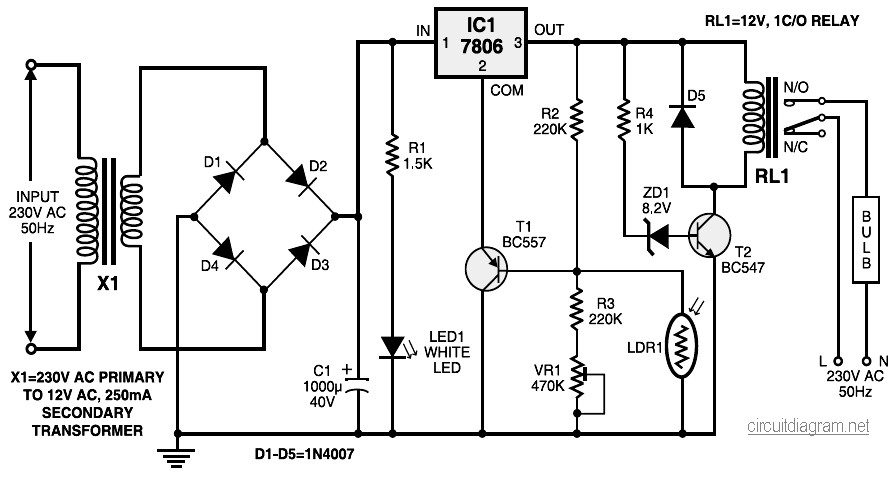
During nighttime, when no light falls on LDR1, it offers a high resistance at the base junction of transistor T1. Consequently, the bias is significantly reduced, and T1 does not conduct. This effectively removes the common terminal of IC1...
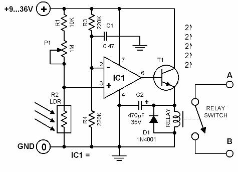
The brightness of the surrounding light controls the function of this circuit. The light sensor used in this circuit is a light-dependent resistor (LDR). This LDR is connected to the non-inverting input of the 741 op-amp IC. Once the...

This is a Xenon Strobe Light circuit that utilizes a Xenon tube to produce various brightness levels. The blinking speed can be finely adjusted to be fast or slow using VR1. The circuit incorporates a Silicon Controlled Rectifier (SCR). The...
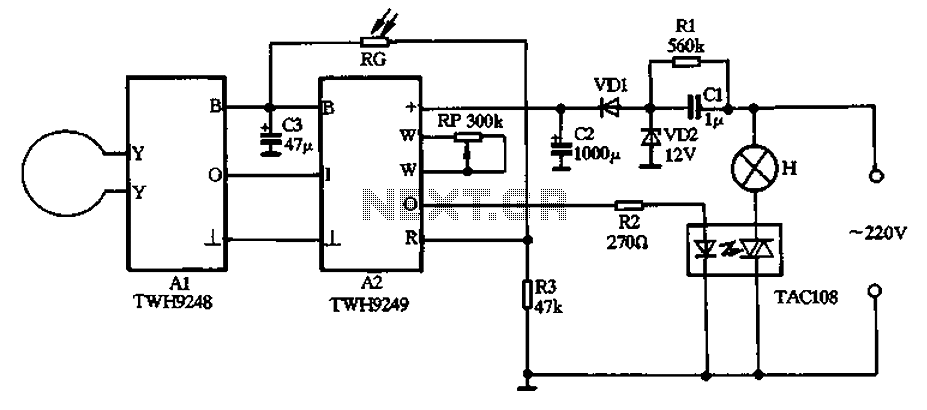
The circuit operates on 220V AC input and utilizes a CL buck converter, a VDI rectifier, and a VD2 regulator along with a filter capacitor (C2) to provide a stable 12V DC output for module A2. Module A2 includes...
This circuit was designed on request and can be useful to those wishing to have, say, a red LED illuminated when an appliance is on and a green LED illuminated when the same appliance is off. Any mains operated...
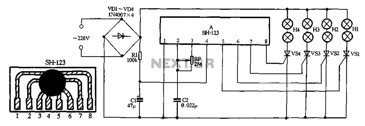
A 220V AC input is processed by a bridge rectifier consisting of diodes VD1 to VD4, which supplies electricity to four lights labeled H1 to H4. The circuit includes a limiting resistor R1 and a filter capacitor C1 to...