
Mono audio panoramic interference (pan pot)
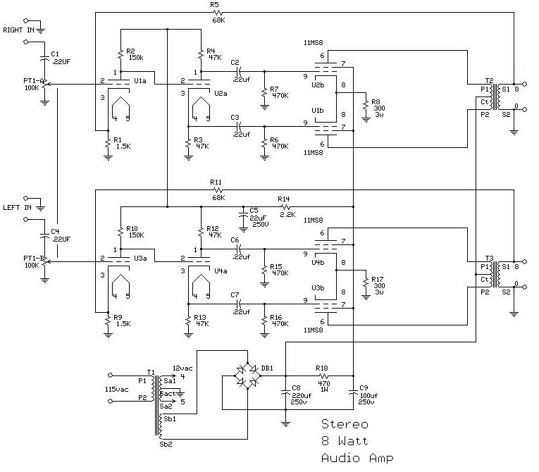
The described circuit is a sophisticated audio processing unit that effectively manipulates mono sound signals within a stereo speaker setup. The design incorporates a potentiometer (P1) that allows precise control over the audio signal's balance between the left and right channels. This feature is particularly beneficial in applications where audio spatialization is critical, such as in professional audio mixing or playback systems.
The input buffer (IC1) plays a vital role in maintaining signal integrity by inverting the input signal and ensuring that the output phase aligns with the intended audio output. This inversion is crucial for preventing phase cancellation that could degrade audio quality. The choice of a 1 kΩ resistor (R1) at the input stage ensures adequate input impedance, allowing for compatibility with various audio sources.
The feedback network formed by the combination of P1, R4, R8, and R9 allows for fine-tuning of the gain characteristics of the operational amplifiers (IC2 and IC3). This feedback mechanism is essential for achieving the desired audio output characteristics, enabling users to adjust the sound profile to their preferences.
The output stage is designed to handle capacitive loads effectively, thanks to the inclusion of series resistors (R7 and R12). This design consideration prevents instability that could arise from driving capacitive elements, ensuring consistent performance across different load conditions.
Coupling capacitors (C3, C6, and C9) are strategically placed to block DC offsets while allowing AC audio signals to pass. Their omission is permissible under certain conditions, highlighting the circuit's flexibility in various applications. The stability capacitors (C2, C5, and C8) are critical for maintaining amplifier performance, particularly at unity gain, where the risk of oscillation is heightened.
Furthermore, the interference minimization capacitors (C1, C4, and C7) are essential for reducing unwanted noise within the specified frequency range. This design feature enhances the overall signal-to-noise ratio, contributing to the circuit's high fidelity.
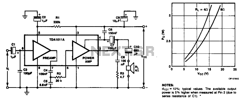
The performance metrics indicate that the circuit is capable of delivering high-quality audio with minimal distortion, making it suitable for professional applications. The specified total harmonic distortion of 0.0014% at 1 kHz indicates excellent linearity and sound reproduction fidelity, which is a critical requirement in high-end audio systems.
The power supply requirement of 18 V and a current draw of approximately 16 mA suggest that the circuit is efficient and can be integrated into various audio systems without significant power overhead. Overall, this circuit design exemplifies a well-engineered solution for audio processing, offering both flexibility and high performance in stereo audio applications.The circuit spectator interference enables implantation mono sound at any point between stereo speakers. When P1 is in the middle of his journey, there is strengthening or weakening of the mark the entrance to the exit in any of the two channels.
When the potentiometer placed elsewhere, away from halfway, the signal in one channel is supported 3dB more than the other. The input stage is a buffer (IC1). Inverts the input signal to ensure compliance with this phase of the output (Next steps' and reverse them the signal they receive to entry).
The resistance value entry identifies to that of R 1 (1 A KO). The output buffer is driven in stereo amplifiers IC2 and IC3. The potentiometer P1, in conjunction with the A3, R4, R8, and A9, affects the routes of feedback and two boosters. This result in any adjustment of P1 to make the opposite metavoles enischysi the two opamps. The series resistors A7 and A12 provide the possibility of output lead capacitive loads. Capacitors coupling C3, C6 and C9 can be omitted if the application for the intended circuit can tolerate continuous diversion trends in output of about 20-30 mv.
The capacitors C2, C5 and C8 ensure stability amplifier, even with unit gain. The capacitors C 1, C4 and C7 minimize any interference r1, which is probably appears within the area 2.5IZ-200KIZ. The performance of the circuit is very good and can be used in High-quality consoles. The total harmonic distortion plus thorythoo the frequency of 1 kHz with a bandwidth of 22 kHz is 0.0014%.
The circuit needs power supply 18 W of power which consumes approximately 16 mA. 🔗 External reference
Related Circuits
The notch filter can be integrated into nearly any receiver to attenuate a specific frequency by more than 30 dB. This filter is particularly useful for diminishing heterodynes and whistles. A notch filter, also known as a band-stop or band-reject...
The 25-watt audio amplifier circuit is powered by a tube circuit. The tube transistor (TR) will amplify the input to approximately 20 watts, while a dual transformer can increase the output to 40 watts. A wide voltage range of...
The primary component of this three-band graphic equalizer is the LM833, manufactured by National Semiconductor. The LM833 features very low noise levels and operates with a bandwidth of 15 MHz. The LM833 operational amplifier is designed to provide high-performance audio...
The monolithic integrated audio amplifier circuit is specifically designed for portable radio and recorder applications, delivering up to 4 W into a 4-ohm load impedance. The power output is close to 6 watts RMS. The monolithic integrated audio amplifier circuit...
The main circuit of the 6-channel mixer consists of six input channels. Channels 1-4 are mono, while channels 5-6 are designed for music use. The number of input channels can be increased as desired. The output of each channel...
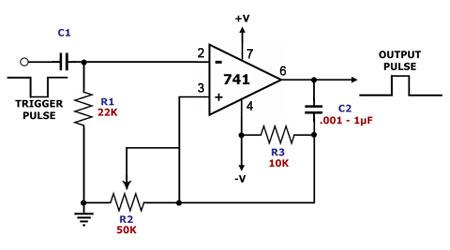
This is a monostable multivibrator circuit that utilizes a single operational amplifier. The primary component of this circuit is the 741, a general-purpose operational amplifier. A monostable multivibrator is a timing circuit that changes its output state when triggered...