
op amp monostable multivibrator
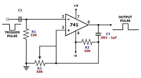
The monostable multivibrator circuit described operates by leveraging the properties of the operational amplifier (op-amp) to generate a precise time delay in response to an input trigger. The 741 op-amp, a widely used component in analog circuits, is configured in a manner that allows it to function as a monostable multivibrator. Upon receiving a negative trigger pulse at its input, the output transitions to a high state, indicating that the circuit has been activated.
In this configuration, capacitor C2 plays a crucial role in determining the timing characteristics of the circuit. The charging process of C2, initiated by the output going high, raises the voltage at the non-inverting terminal of the op-amp. The resistor R2, connected in series with C2, influences the rate at which C2 charges and discharges, thereby defining the duration of the high output state. The time constant of the circuit, which is a product of R2 and C2, directly correlates to the pulse width of the output signal.
Once the capacitor C2 reaches a certain voltage threshold, it begins to discharge, causing the voltage at the non-inverting input to drop below that of the inverting input. This transition results in the output of the op-amp reverting to a low state, completing the cycle of the one-shot operation. The design of the circuit allows for flexibility in adjusting the pulse width by selecting appropriate values for R2 and C2, making it suitable for various applications such as pulse width modulation, frequency division, and signal conditioning.
Overall, the monostable multivibrator circuit using the 741 op-amp is an effective solution for generating time-delayed output signals in response to input triggers, with a variety of practical applications in electronic systems.This is a monostable multivibrator circuit that employs a single op amp. The main component of this circuit is the 741, a general-purpose operational amplifier. A monostable multivibrator is a timing circuit that changes state once triggered, but returns to its original state after a certain time delay. It got its name from the fact that only one of its output states is stable. It is also known as a `one-shot`. A negative trigger pulse at the input forces the output of the op amp to logic `high`. This charges up C2 which keeps the non-inverting input of the op amp temporarily higher than the inverting input, maintaining the output high for a certain period of time. Eventually C2 discharges to ground and the op amp output swings back to logic `low`. The duration of the pulse is defined by R2 and C2. The `one-shot` has several applications, which include dividing the frequency of the input signal and converting an irregular input pulse to a uniform output pulse.
🔗 External reference
Related Circuits
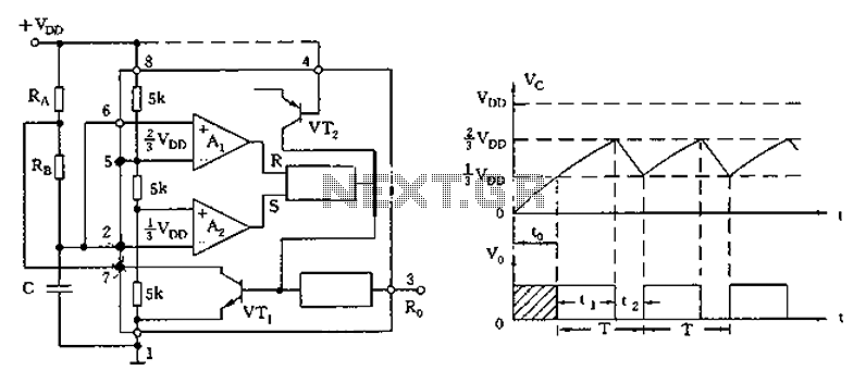
The circuit diagram illustrates the 555 timer (or 556 timer in half configuration) configured in astable multivibrator mode. It features three resistive and capacitive elements connected as shown. In one-shot mode, the trigger terminal (pin 2) is connected to...
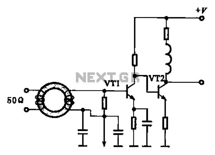
A broadband high-frequency amplifying circuit is primarily composed of a high-frequency matching transformer and an amplifying transistor. This circuit is designed to handle large high-frequency signals. The input of the amplifier circuit utilizes a matching transformer to ensure that...
The schematic diagram below illustrates a basic sample-and-hold circuit utilizing the CA3140 as the readout amplifier for the memory capacitor. The CA3080A is also employed in the design. The sample-and-hold circuit is a crucial component in analog-to-digital conversion systems, allowing...
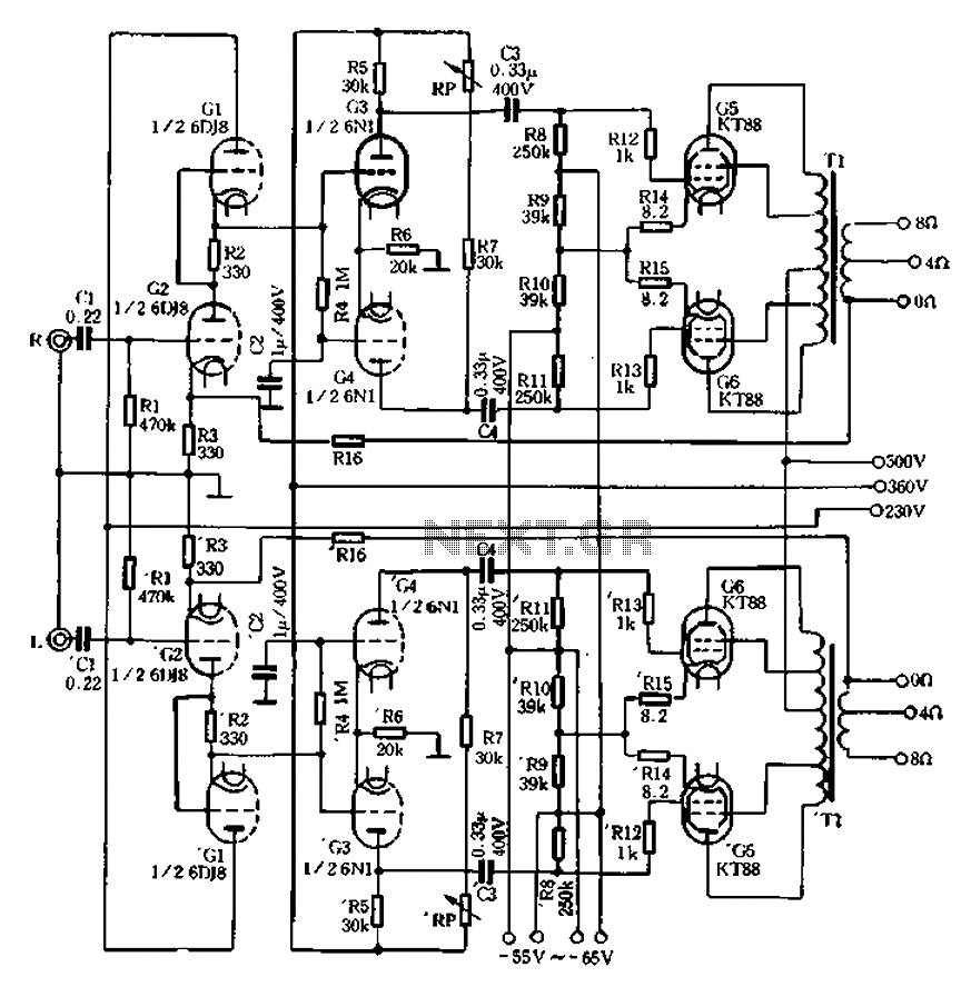
Due to the use of high-quality materials and advanced technology, the output transformer of the machine achieves a frequency response ranging from 10Hz (0.8dB) to 50Hz (1dB), enhancing overall performance. The aircraft power supply voltage section, illustrated in Figure...
This circuit is basically simple and easy to build, it uses two transistors as active components and a few passive components like resistors, capacitors and two LEDs. The circuit makes use of the MPS2222 transistor. You can use any...
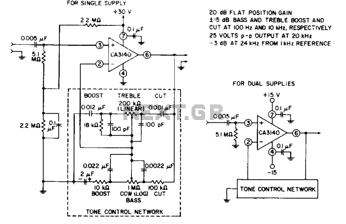
The circuit effectively utilizes the high slew rate, wide bandwidth, high input impedance, and high output voltage capability of the CA3140 BiMOS operational amplifier. The wideband gain of this circuit is equal to the ultimate boost or cut plus...