
Mono stable with 555 and relay
In the idle state, the output at pin 3 will be at ground and the relay deactivated. The trigger input (pin 2) is held high by the 100K resistor and both capacitors are discharged. When the button is closed, the 0.1uF cap will charge through the button and the 100K resistor which causes the voltage at pin 2 to move low for a few milliseconds. The falling voltage at pin 2 triggers the 555 and starts the timing cycle. The output at pin 3 immediately moves up to near the supply voltage (about 10.4 volts for a 12 volt supply) and remains at that level until the 22 uF timing capacitor charges to about 2/3 of the supply voltage (about 1 second as shown). Most 12 volt relays will operate at 10.4 volts; if not, the supply voltage could be raised to 13.5 or so to compensate. The 555 output will supply up to 200mA of current, so the relay could be replaced with a small lamp, doorbell, or other load that requires less than 200mA. When the button is released, the 0.1uF capacitor discharges through the 100K and 2K resistors. The diode across the 100K resistor prevents the voltage at pin 2 from rising above the supply voltage when the cap discharges. The 2K resistor in series with the 22uF cap limits the discharge current from pin 7 of the timer. This resistor may not be necessary, but it's a good idea to limit current when discharging capacitors across switch contacts or transistors.
The described circuit utilizes the 555 timer in monostable mode, where it functions as a timer that produces a single output pulse in response to a trigger input. The circuit is designed to control a relay, allowing for the activation of various loads for a specified duration after a momentary push button is pressed.
In its idle state, the output at pin 3 of the 555 timer remains low, keeping the relay deactivated. The trigger input at pin 2 is maintained in a high state due to the 100K pull-up resistor, ensuring that the timer remains inactive until the push button is pressed. Upon pressing the button, the 0.1uF capacitor begins to charge through the closed switch and the 100K resistor. This charging process causes the voltage at pin 2 to drop below the threshold level, triggering the timer and initiating the timing cycle.
The output at pin 3 transitions to a high state, approximately equal to the supply voltage, which is sufficient to energize the relay. The timing period is determined by the values of the timing capacitor (22uF) and the resistor network associated with the discharge path. As the timing capacitor charges, the voltage at pin 6 rises until it reaches approximately 2/3 of the supply voltage, at which point the output at pin 3 will return to a low state, deactivating the relay.
The circuit also incorporates protective components to manage voltage levels and discharge paths. The diode placed across the 100K resistor serves to prevent any back voltage from affecting the trigger input during the capacitor's discharge cycle. The additional 2K resistor in series with the timing capacitor is a precautionary measure to limit the discharge current from pin 7, thus protecting the timer and ensuring reliable operation.
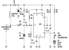
Overall, this configuration provides a flexible and efficient means of controlling loads with a predetermined timing sequence, suitable for applications requiring momentary activation of devices such as relays, lamps, or other low-power electronic components.The two circuits below illustrate using the 555 timer to close a relay for a predetermined amount of time by pressing a momentary N/O push button. The circuit on the left can be used for long time periods where the push button can be pressed and released before the end of the timing period.
For shorter periods, a capacitor can be used to isolate the switch so that only the initial switch closure is seen by the timer input and the switch can remain closed for an unlimited period without effecting the output. In the idle state, the output at pin 3 will be at ground and the relay deactivated. The trigger input (pin 2) is held high by the 100K resistor and both capacitors are discharged. When the button is closed, the 0.1uF cap will charge through the button and the 100K resistor which causes the voltage at pin 2 to move low for a few milliseconds. The falling voltage at pin 2 triggers the 555 and starts the timing cycle. The output at pin 3 immediately moves up to near the supply voltage (about 10.4 volts for a 12 volt supply) and remains at that level until the 22 uF timing capacitor charges to about 2/3 of the supply voltage (about 1 second as shown).
Most 12 volt relays will operate at 10.4 volts, if not, the supply voltage could be raised to 13.5 or so to compensate. The 555 output will supply up to 200mA of current, so the relay could be replaced with a small lamp, doorbell, or other load that requires less than 200mA.
When the button is released, the 0.1uF capacitor discharges through the 100K and 2K resistors. The diode across the 100K resistor prevents the voltage at pin 2 from rising above the supply voltage when the cap discharges. The 2K resistor in series with the 22uF cap limits the discharge current from pin 7 of the timer. This resistor may not be necessary, but it's a good idea to limit current when discharging capacitors across switch contacts or transistors.
🔗 External reference
Related Circuits
Remove the 6 mm screw that secures the lower rear fairing cover. This cover is the black plastic piece to which the spark plug protectors are attached. Only the machine screw should be removed; do not detach the lower...
The tool is based on a NE555 (or LM555) timer i.c., wired as an astable multivibrator. The frequency of the multivibrator is determined by the value of the unknown capacitor Cx. The circuit can be fed by a small...
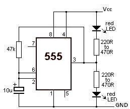
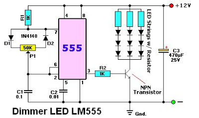
This LED flasher circuit utilizes the 555 timer integrated circuit (IC). The circuit diagram is straightforward and requires only a few external components. When operational, the red LEDs will flash sequentially at a predetermined frequency, similar to the indicators...
The sections available in this datasheet cover general design considerations for the 555 timer, frequently asked application questions (FAQ), design formulas, and examples of innovative applications. Examples of applications include a Missing Pulse Detector, Pulse Width Modulation (PWM), Tone...
The LM555 timer IC can be utilized in various electronic projects, including the creation of an analog timer. According to the datasheet, the LM555 is versatile and can be adjusted to set timers based on specific requirements. The schematic...
This mini metronome provides a linearly scaled output with a range of 40 to 208 beats per minute. The transistors Q1 and Q2 facilitate the linear frequency variation of IC1. The described mini metronome circuit utilizes an integrated circuit (IC1)...