
Mini Metronome by 555 Timer/Oscillator IC
The described mini metronome circuit utilizes an integrated circuit (IC1) that serves as the core timing element, generating a pulse signal at variable frequencies corresponding to the selected beats per minute (BPM). The operational range from 40 to 208 BPM allows for versatile applications, from practice sessions for musicians to tempo guidance for various rhythmic activities.
Transistors Q1 and Q2 are configured in a manner that enables them to modulate the output frequency of IC1 linearly. This configuration can be achieved through a feedback mechanism where the transistors adjust the charge and discharge times of a timing capacitor, which is connected to the IC. The precise control of these transistors ensures that the BPM can be adjusted smoothly without abrupt changes, providing a stable and reliable tempo.
The circuit may also include additional components such as resistors and capacitors to set the timing characteristics of IC1. A potentiometer could be incorporated to allow users to fine-tune the BPM setting easily. Furthermore, an LED indicator may be added to visually represent the tempo, flashing in sync with the output beats.
Power supply considerations are essential for the circuit, with a typical requirement of a stable voltage source, often provided by batteries or a DC power supply. Proper decoupling capacitors should be placed near the power pins of IC1 to minimize noise and ensure stable operation.
Overall, this mini metronome circuit is an effective tool for maintaining tempo, and its straightforward design allows for easy assembly and modification, making it suitable for both hobbyists and professional applications in music and rhythm training.This mini metronome gives a linear scaled output and 40 to 208 beats per minute. 1- Q1 and Q2 transistors provide linear frequency variation of IC1 depend.. 🔗 External reference
Related Circuits
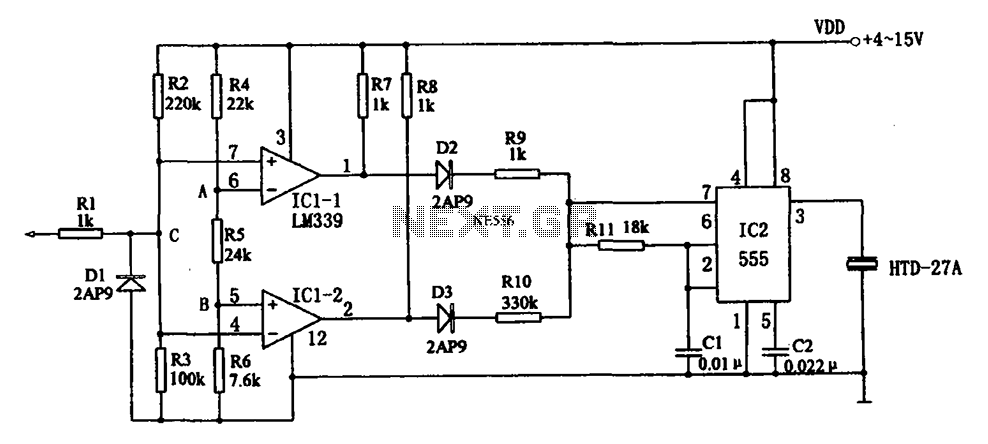
The acoustic logic level probe circuit consists of a voltage comparator, multivibrator, piezoelectric ceramics (HTD), and other components. The configuration of the audio circuit determines the frequency of the sound level to assess the logic levels of TTL or...
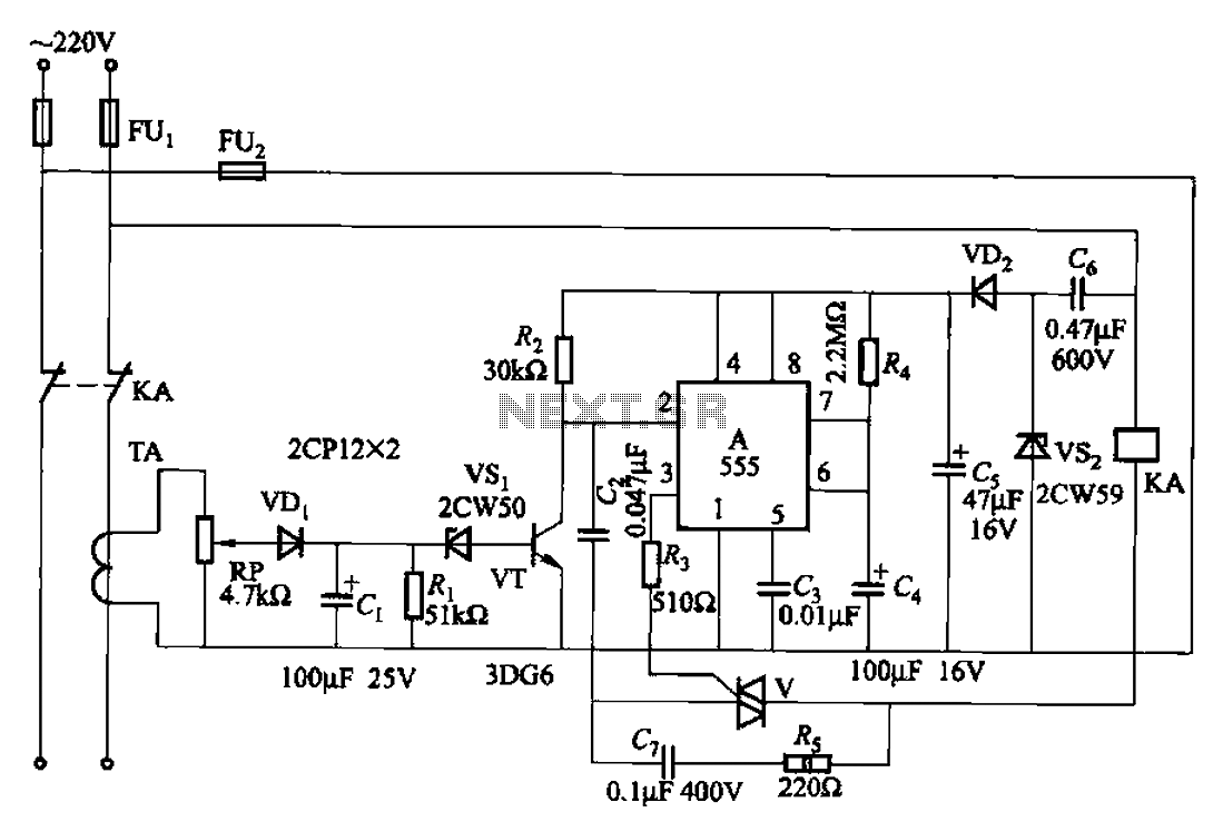
The 555 limit circuit, which is an integrated electrical circuit, is designed to manage large electrical loads. It automatically disconnects power when the load exceeds a predetermined threshold. Once the load is reduced below this threshold, power is restored...
It is a miniature 10/100-MbBit Ethernet module that includes an integrated microcontroller. The price is less than $60. With its minimal dimensions of 1.38 in. x 2.16 in. (34.5 mm x 54 mm), the communications module can be used...

This circuit is a touch switch circuit, similar to a touch door alarm. It utilizes a 555 timer as the core component of the touch switch circuit. The operation begins when the plate is touched, triggering the 555 timer....
This instrument is a sensitive analyzer that detects changes in frequency and the width of an acoustic signal. The brightness of the LED that activates at any given moment is proportional to the width of the signal, while the...

This circuit operates as an astable multivibrator. With switch S9, an octave can be chosen. The tones are set by P1 to P8. Pressing S1 to S8 displays the corresponding note; pressing two buttons at the same time gives...
Warning: include(partials/cookie-banner.php): Failed to open stream: Permission denied in /var/www/html/nextgr/view-circuit.php on line 713
Warning: include(): Failed opening 'partials/cookie-banner.php' for inclusion (include_path='.:/usr/share/php') in /var/www/html/nextgr/view-circuit.php on line 713