
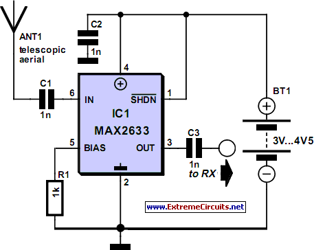
monostable multivibrator with a 74hc123 chip

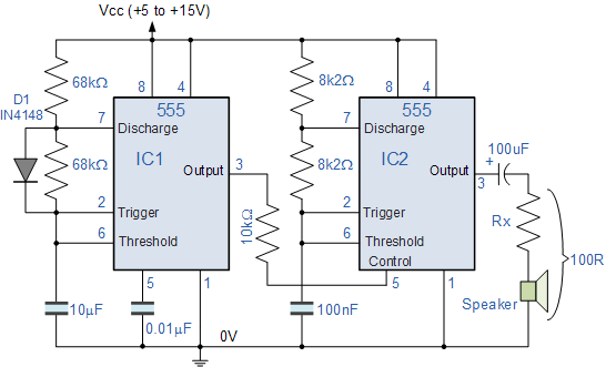
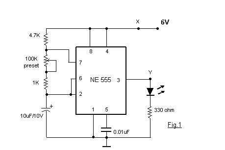
The monostable multivibrator, often implemented using a 555 timer IC in monostable mode, serves as a pulse generator that produces a single output pulse when triggered. In this application, the output from the infrared (IR) circuit acts as the trigger signal for the 555 timer. Upon receiving the trigger signal, the timer generates a high output for a predetermined time interval, which is set by external resistor and capacitor components.
To design this circuit, the following components are essential:
1. **555 Timer IC**: This is the core component of the monostable multivibrator. It has three main pins of interest: the trigger pin (Pin 2), the output pin (Pin 3), and the threshold pin (Pin 6).
2. **Resistor (R)**: This resistor is connected between the discharge pin (Pin 7) and the supply voltage (Vcc). It plays a crucial role in determining the duration of the output pulse.
3. **Capacitor (C)**: The capacitor is connected between the threshold pin (Pin 6) and ground. The time period for which the output remains high is calculated using the formula T = 1.1 * R * C, where T is the time in seconds.
4. **Relay**: The relay is connected to the output pin (Pin 3) of the 555 timer. It allows for switching of higher voltage or current loads based on the low-power output signal from the timer.
5. **Diode**: A flyback diode should be placed in parallel with the relay coil to protect the circuit from back EMF generated when the relay is de-energized.
The circuit operates as follows: When the IR circuit detects an object or an event, it sends a trigger pulse to the 555 timer. This pulse causes the output pin to go high, energizing the relay for the duration set by the resistor and capacitor. Once the time elapses, the output returns to low, deactivating the relay.
Proper power supply considerations must be made to ensure the 555 timer operates within its specified voltage range, typically between 4.5V to 15V. Additionally, the values of R and C should be selected based on the desired timing interval, taking into account the application requirements.
This configuration provides a reliable way to control a relay based on an IR signal, with adjustable timing capabilities to suit various applications.I am trying to build a monostable multivibrator so that I can use the output of an IR circuit to trigger a relay for n seconds thru the one shot. I found a chip .. 🔗 External reference
Related Circuits
A high-performance RF amplifier designed for the entire VHF broadcast and PMR band (100-175 MHz) that can be constructed without the need for specialized test equipment. The grounded-gate configuration offers inherent stability without requiring neutralization, provided that appropriate PCB...
Electronics tutorial about the 555 oscillator and how the 555 oscillator can be used as a 555 astable oscillator circuit to generate square wave waveforms. The 555 timer IC is a versatile and widely used component in electronics, particularly for...
It is advisable to prototype the entire circuit using a breadboard. This method simplifies the process significantly compared to attempting to determine the connections on a small printed circuit board. Prototyping a circuit on a breadboard allows for easy modifications...

A low-cost vacuum cleaner system based on the P89LPC901 is introduced in this application note. The design hardware and software are thoroughly discussed. This system can also guide the design of other universal motor driving systems that require robust...
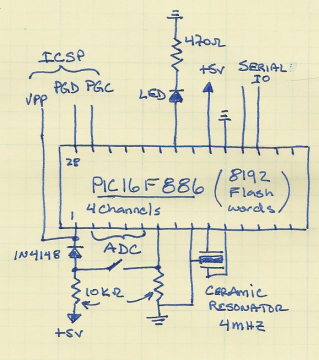
This project includes a few modifications from the Single Chip, Four Channel Datalogger article, so minimal detail will be provided. Below is the schematic. The changes from Dan's datalogger include the use of the PIC16F886, which is pin-compatible with...

This free-running square-wave oscillator utilizes two NPN transistors. The output frequency is approximately 300 Hz with the specified component values. The circuit operates as a basic oscillator, generating a square wave output through the interaction of two NPN transistors. The...