
555 Oscillator Tutorial (Astable Multivibrator)
The 555 timer IC is a versatile and widely used component in electronics, particularly for generating precise timing and waveform generation. The astable mode of the 555 timer allows it to function as an oscillator, producing continuous square wave signals without the need for external triggering.
In an astable configuration, the 555 timer operates between two unstable states, continuously switching between them. The circuit typically consists of two resistors (R1 and R2) and a capacitor (C1) connected to the 555 timer. The resistors determine the charge and discharge times of the capacitor, which in turn dictate the frequency and duty cycle of the output waveform.
The output frequency (f) of the square wave can be calculated using the formula:
\[ f = \frac{1.44}{(R1 + 2R2) \times C1} \]
Where:
- R1 is the resistor connected between Vcc and the discharge pin (pin 7).
- R2 is the resistor connected between the discharge pin and the threshold pin (pin 6).
- C1 is the capacitor connected between the threshold pin and ground.
The duty cycle percentage, which indicates the proportion of time the output is high versus low, can be calculated with the formula:
\[ Duty Cycle = \frac{R2}{R1 + 2R2} \times 100 \]
The output frequency and duty cycle can be adjusted by varying the values of R1, R2, and C1, allowing for a wide range of applications. The output of the 555 timer in astable mode can be used to drive LEDs, create clock pulses for digital circuits, or generate audio tones.
To implement the circuit, the 555 timer should be connected as follows:
- Connect pin 1 (GND) to ground.
- Connect pin 2 (Trigger) to pin 6 (Threshold).
- Connect pin 3 (Output) to the desired load or output device.
- Connect pin 4 (Reset) to Vcc to disable the reset function.
- Connect pin 5 (Control Voltage) to ground through a capacitor (typically 0.01 µF) for stability.
- Connect pin 6 (Threshold) to pin 2 (Trigger) and to R2.
- Connect pin 7 (Discharge) to R1 and to C1.
- Connect pin 8 (Vcc) to the positive supply voltage.
By carefully selecting the resistor and capacitor values, the 555 astable oscillator can be tailored to meet specific frequency and duty cycle requirements for various electronic applications.Electronics Tutorial about the 555 Oscillator and How the 555 Oscillator can be used as a 555 Astable Oscillator Circuit to Generate Square Wave Waveforms.. 🔗 External reference
Related Circuits
A sawtooth wave oscillator is utilized in cathode ray tube deflection circuitry, in a PWM modulator, or in analog to digital conversion applications. The sawtooth wave oscillator generates a waveform that linearly rises and then sharply drops, resembling the...
In this circuit, the 555 timer is utilized in an innovative manner as a voltage-controlled switch. The widely used NE555 can perform effectively in various applications. The 555 timer, a versatile integrated circuit, is commonly employed in timer, delay, pulse...
I am attempting to construct a Hartley oscillator using a bypassed common emitter configuration. The goal is to achieve oscillation at a frequency of 200 kHz with a peak-to-peak voltage of 2 V, utilizing a BC547B transistor. The Hartley oscillator...
The 27MHz quartz crystal oscillator circuit is illustrated in figure 1. The biasing circuit consists of resistors R1, R2, and R3, while C6 serves as the bypass capacitor. The partial voltage circuit includes capacitors C1, C2, C3, and C4...
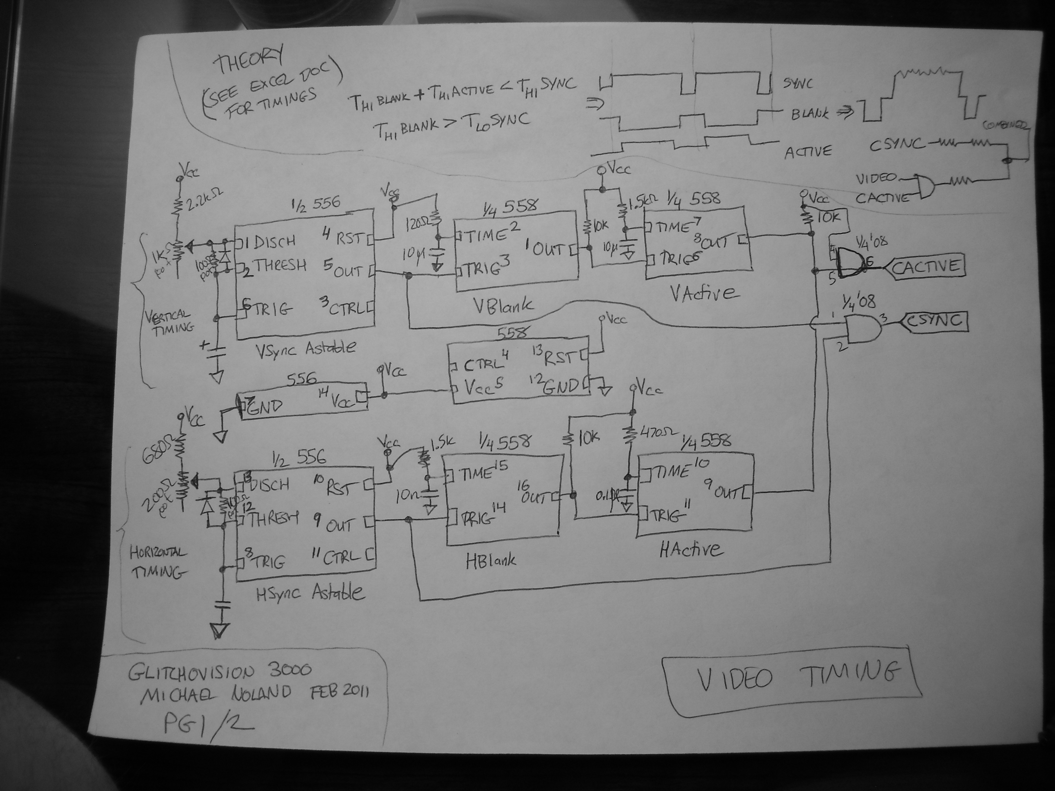
This entry describes a four-step sequencer that controls an Atari Punk synth, accompanied by a grayscale NTSC video visualization of the output audio. The system is constructed using two 558 quad-timers and two 556 dual-timers. The video quality may...

The circuit utilizes a 555 timer IC to create a lighting group delay effect, as illustrated in Figure 2-46. It consists of the 555 IC along with a resistor and capacitor configuration that establishes the delay. The circuit remains...
Warning: include(partials/cookie-banner.php): Failed to open stream: Permission denied in /var/www/html/nextgr/view-circuit.php on line 713
Warning: include(): Failed opening 'partials/cookie-banner.php' for inclusion (include_path='.:/usr/share/php') in /var/www/html/nextgr/view-circuit.php on line 713