
Radiant Oscillator
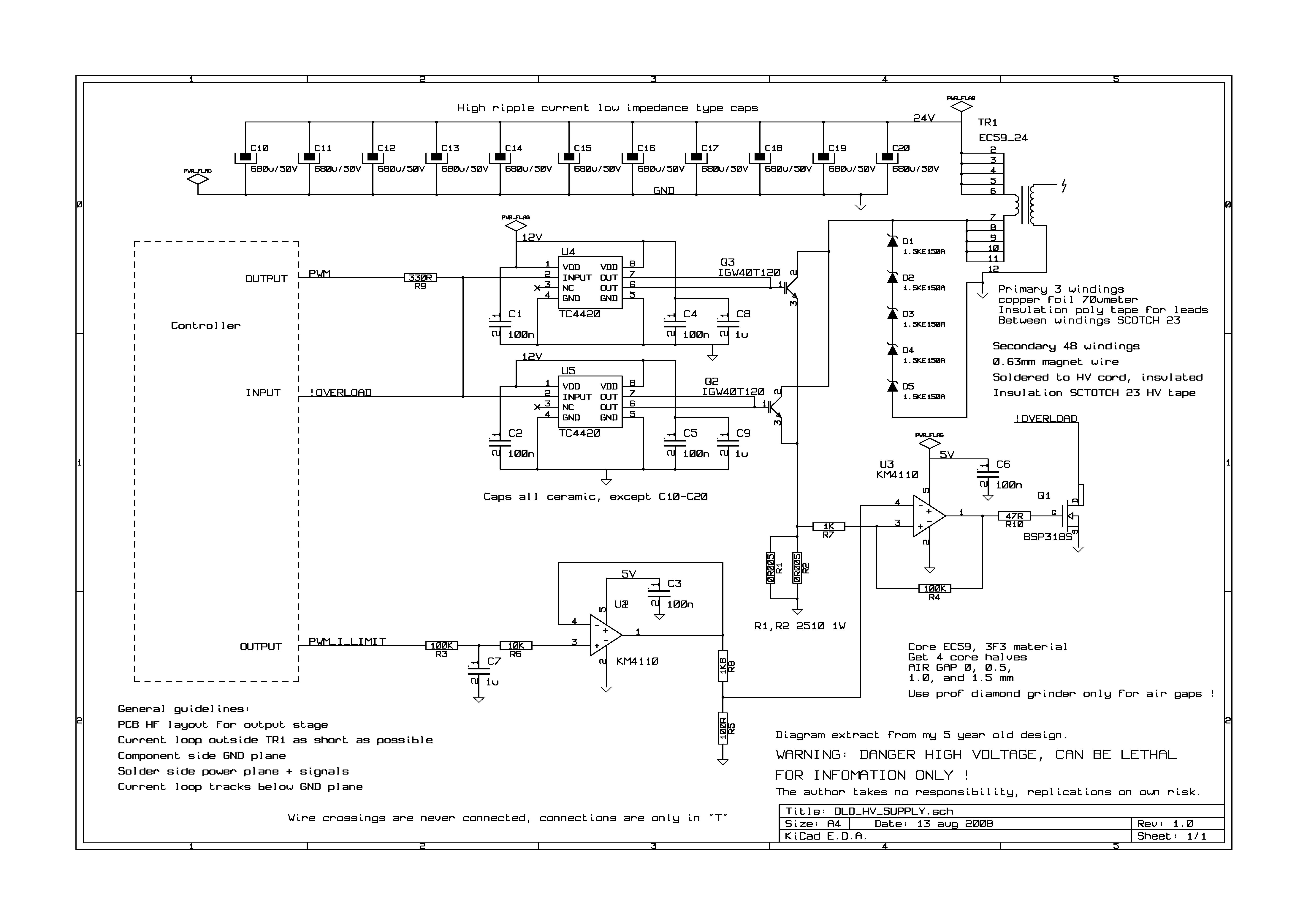
The described circuit appears to be a power supply or lighting system that utilizes a 36V input, drawing a current of 500mA to achieve a certain luminosity. The front section of the circuit likely includes a light-emitting component, such as an LED array or a compact fluorescent lamp, designed to produce brightness equivalent to a traditional 240V incandescent bulb. This suggests an efficient design, as the 20-watt rating indicates that the circuit is optimized for lower power consumption while delivering substantial light output.
The back section of the circuit incorporates a charging mechanism, which is essential for maintaining the operation of the system, particularly if it is intended for portable applications or battery-powered devices. This charging circuit may include components such as a voltage regulator, a rectifier, and possibly a battery management system to ensure safe and efficient charging.
Overall, the design emphasizes efficiency, with the ability to operate at a lower voltage while still achieving high brightness levels, making it suitable for various applications where energy conservation is a priority. The integration of a charging capability further enhances its functionality, allowing for continuous operation without the need for frequent battery replacements.here is a pic running 36v 500ma on the front, 36v charging on the back. Brightness is approaching level of a 240v globe, considering its a 20 watt.. 🔗 External reference
Related Circuits
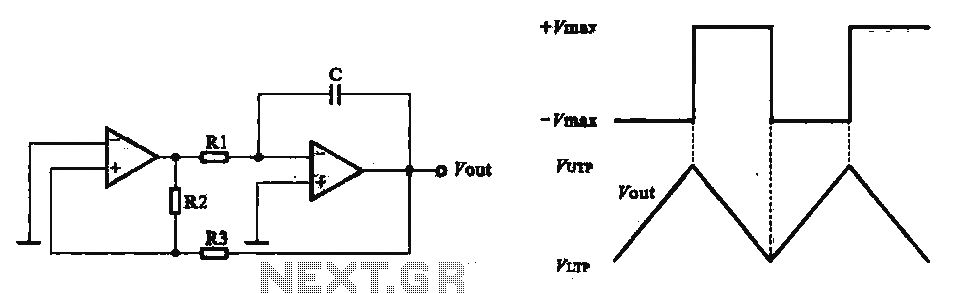
This circuit utilizes two operational amplifiers configured as triangular wave oscillators. It demonstrates a practical application of a relaxation oscillator that employs a voltage comparator to execute the switching function. The schematic in FIG. 2 illustrates the composition of...
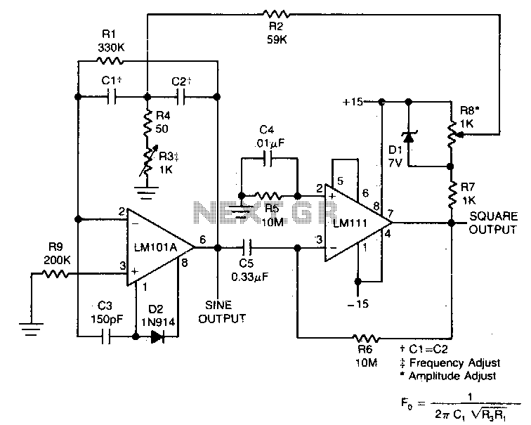
This circuit will provide both a sine and square wave output for frequencies ranging from below 20 Hz to above 20 kHz. The frequency of oscillation can be easily adjusted by changing a single resistor. This circuit is designed to...
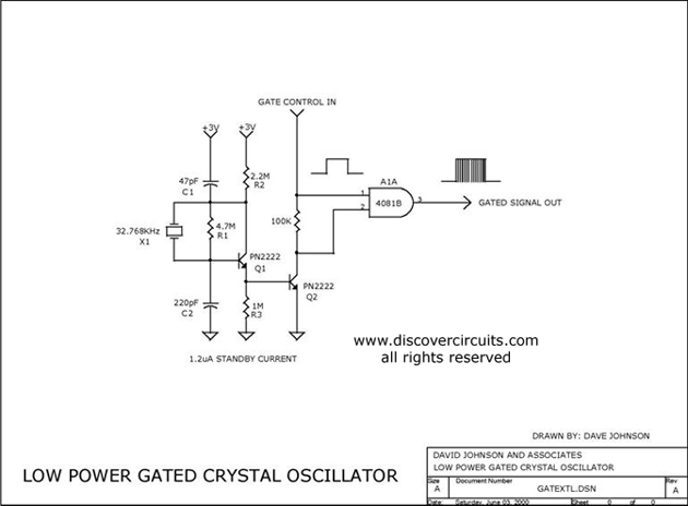
The circuit controls the output of a continuously operating 32KHz crystal oscillator, directing it to the input of a C-MOS buffer when clock pulses are required. This technique addresses the issue of a slow-starting crystal oscillator by maintaining the...
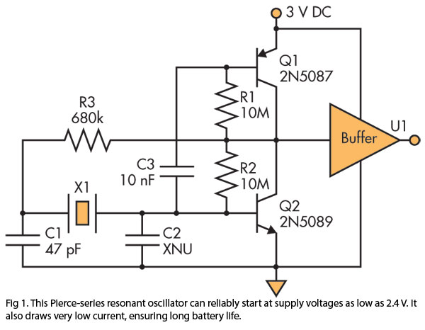
A Pierce (crystal) oscillator designed to deliver a stable clock signal for a minimum duration of one year when powered by battery voltages as low as 2.4 V. The Pierce oscillator circuit is a type of crystal oscillator that utilizes...
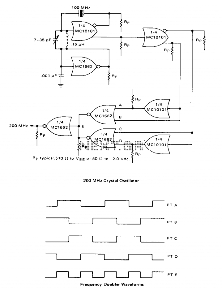
A high-speed oscillator can be created by integrating an MECL 10 crystal oscillator with an MECL III frequency doubler. One section of the MC10101 is configured as a 100 MHz crystal oscillator, with the crystal placed in series within...
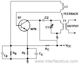
An Armstrong Oscillator is a type of oscillator that utilizes a tickler coil to provide feedback from the tank circuit. This oscillator generates a sine-wave output with constant amplitude and fairly constant frequency within the RF range. Inductor L1...
Warning: include(partials/cookie-banner.php): Failed to open stream: Permission denied in /var/www/html/nextgr/view-circuit.php on line 713
Warning: include(): Failed opening 'partials/cookie-banner.php' for inclusion (include_path='.:/usr/share/php') in /var/www/html/nextgr/view-circuit.php on line 713