
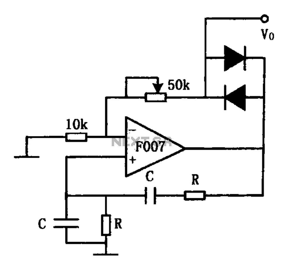
F007 stable sine wave oscillator circuit diagram
The stable sine wave oscillator circuit operates on the principle of negative feedback to regulate its output. The design typically consists of an amplifier stage where the gain is set to a level that allows for sustained oscillation. The circuit's stability is critical; thus, it is essential to maintain the loop gain within specific limits.
The two diodes in the circuit play a crucial role in the feedback mechanism. When the output voltage falls below a specific threshold, the reverse-biased diode effectively removes negative feedback, which allows the gain to increase and the output voltage to rise. This action continues until the output voltage exceeds the threshold, at which point the diode becomes forward-biased. This transition reduces the gain, leading to a decrease in output voltage, thereby creating a self-regulating oscillation cycle.
The potentiometer included in the circuit allows for fine-tuning of the output amplitude and distortion. By adjusting the resistance, the user can modify the feedback level, which directly impacts the output waveform's characteristics. This feature is particularly useful in applications requiring precise control over the output signal.
The frequency of oscillation is determined by the values of the resistor and capacitor in the circuit. The relationship is defined by the equation f0 = 1/(2πRC), where f0 represents the frequency of oscillation, R is the resistance, and C is the capacitance. By selecting appropriate values for R and C, the desired frequency can be achieved, making this circuit versatile for various applications in signal generation and waveform synthesis.
This stable sine wave oscillator circuit can be implemented in various electronic applications, such as audio signal generation, waveform shaping, and clock pulse generation. Its design ensures reliability and stability, making it suitable for both experimental and commercial use. As shown for the stable sine wave oscillator circuit. In order to obtain stable oscillation, the loop gain of claim 1. If the gain is too large, the waveform distortion; if the gain is too small, will appear to stop vibration. This circuit uses two diodes to stabilize oscillation. When the output voltage is too low, the diode is turned off, the negative feedback is cut off, the loop gain is increased, the output voltage is increased. When the output reaches a certain value, the diode is turned on, the loop gain is reduced. Output voltage decreases, and so forth, so that the output amplitude stability at a certain value. FIG potentiometer used to adjust the output amplitude and distortion. The oscillation frequency of the circuit is determined by the resistor R and the capacitor C, its size is:f0 1/2 RC.
Related Circuits
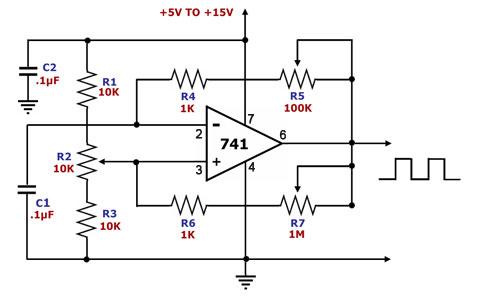
This is a square wave generator circuit. The primary component of this circuit is the 741, a general-purpose operational amplifier. The circuit operates with a single power supply voltage (Vs) that can vary between +5V and +15V. The square...
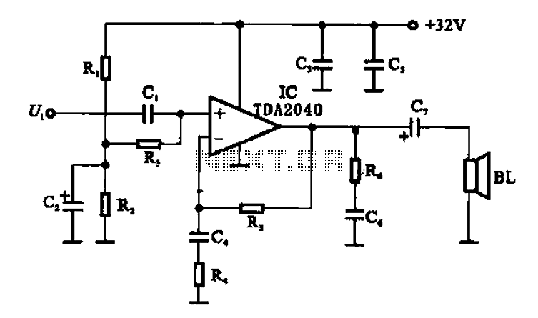
An integrated power amplifier TDA2040 is used in an OTL (Output Transformer-Less) power amplifier circuit, which operates with a +3V single supply as the working voltage. This circuit has a voltage gain of 30 dB (approximately 32 times magnification),...
The following circuit illustrates the sensor circuit diagram for automatic room lights. This circuit is based on the CD4017 integrated circuit (IC) and features the use of two light-dependent resistors (LDRs). The automatic room light circuit utilizes the CD4017 decade...
This circuit displays a sound generator that simulates the siren of a British police car. The circuit is constructed using two timer IC 555. The sound generator circuit designed to simulate a British police car siren utilizes two 555 timer...
The photocell photoelectric tracking circuit is configured with two identical photoelectric cells that serve as light-receiving devices. When the incident light intensity is equal, the system is able to track in a predetermined manner. If there is a slight...
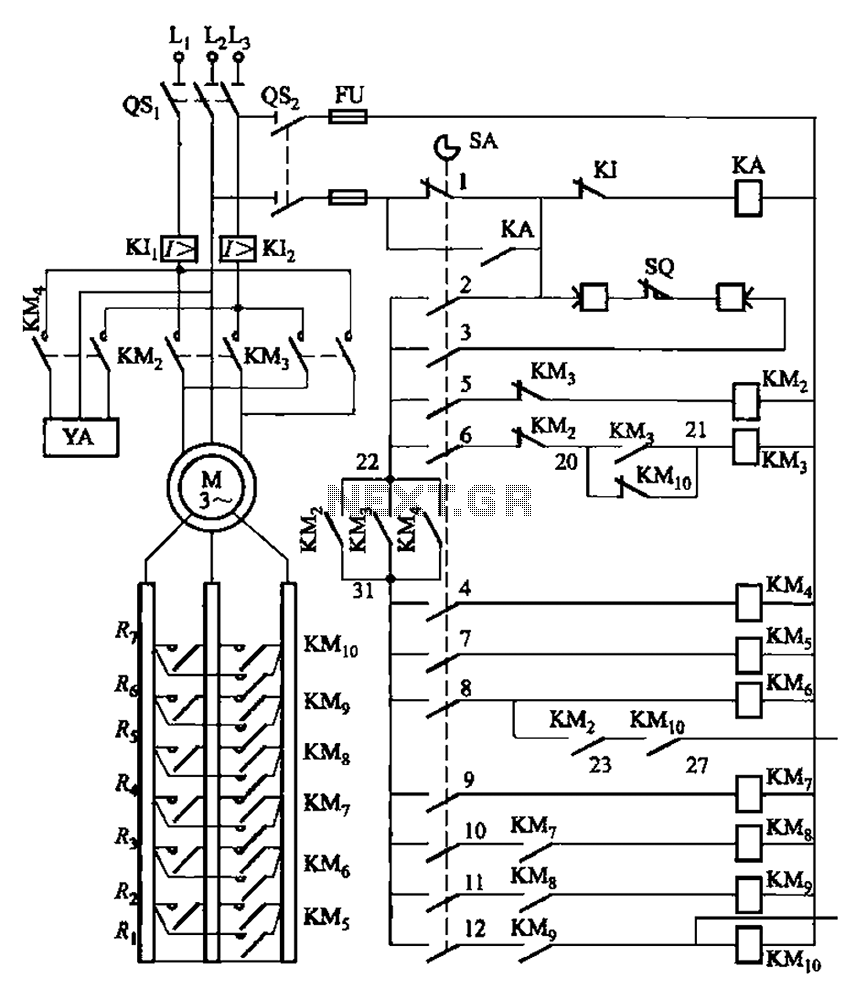
The system is managed by the master controller LKl-12/90 and a magnetic disk control unit PQR10A, which includes a control circuit. The cam control device SA is responsible for contact closure, as indicated in Table 8-5. The main electrical...
Warning: include(partials/cookie-banner.php): Failed to open stream: Permission denied in /var/www/html/nextgr/view-circuit.php on line 713
Warning: include(): Failed opening 'partials/cookie-banner.php' for inclusion (include_path='.:/usr/share/php') in /var/www/html/nextgr/view-circuit.php on line 713